Dynaco MkIV reformed 2014.
Dynaco-MkIV-reformed-1-onbench-feb2015.jpg
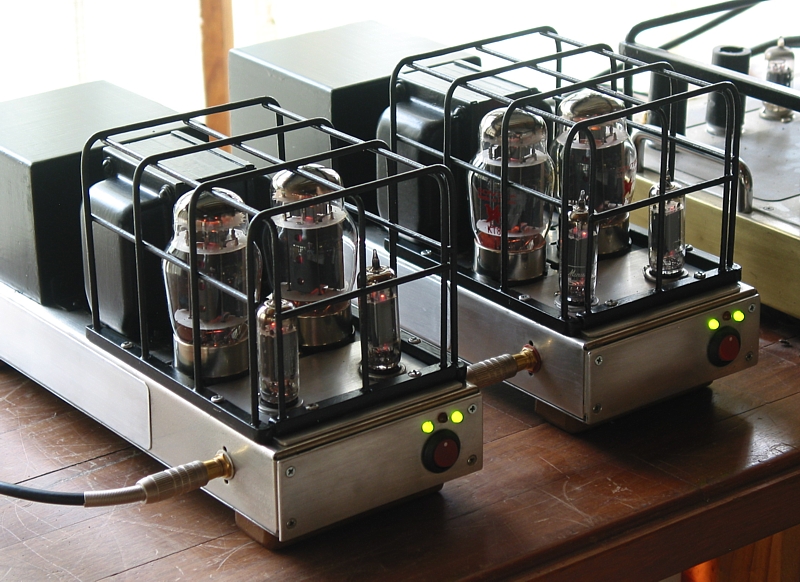
Fig 1. Pair of totally re-engineered Dynaco MkIV, completed 2015.

This web page contains :-
Many notes and explanations about completely re-engineering a pair of 1960 Dynaco MkIV tube amps.
Fig 1. Picture of two 45 Watt Dynaco MkIV tubed monobloc amps with 2 x 6CG7 for input/driver stages
and 2 x KT88 output tubes.
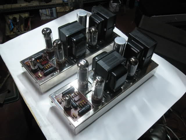
Fig 2. Picture of mint condition pair of Dynaco MkIV mono amps.
NOTE.This picture is from elsewhere on Internet. The original pair of MkIV used for this re-engineering
project were in much worse condition than shown in Fig 2.
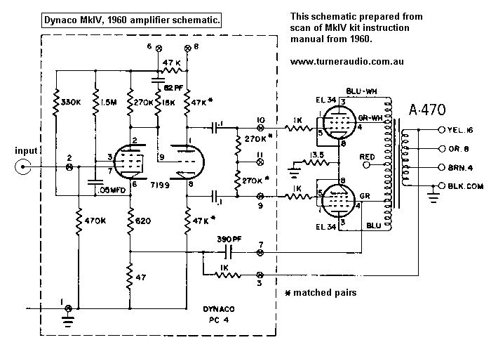
Fig 3. Original 1960 MkIV amplifier schematic.
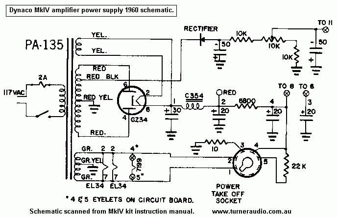
Fig 4. Original 1960 MkIV PSU schematic.
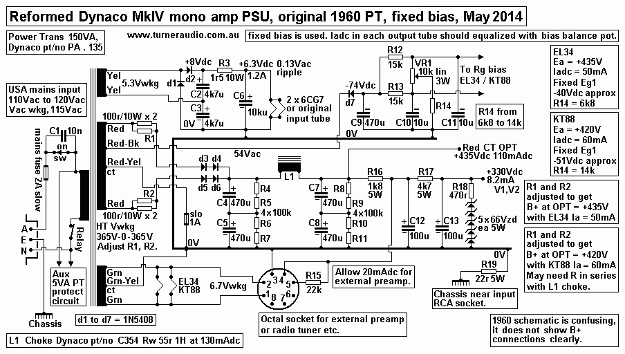
Fig 5. Improved schematic for MkIV PSU using original 1960 power transformer.
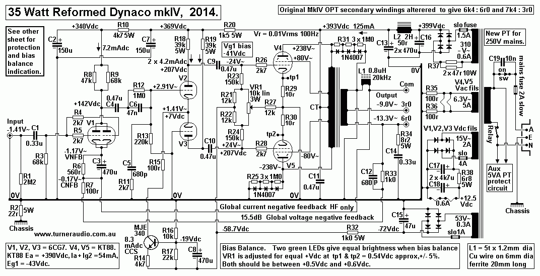
Fig 6. Schematic of Reformed MkIV Amp including PSU with replacement PT
and use of 2 x 6CG7 and 2 x KT88.
Table 1 and Table 2. Tabled load matches for re-configured secondaries of 1960 MkIV OPTs.
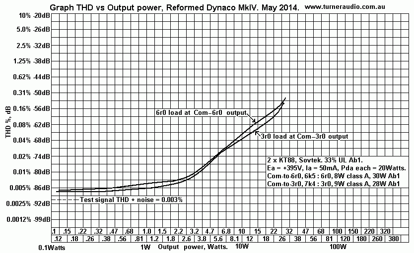
Fig 7. Graph of THD versus Output Power for the two amp output terminals for nominal load
values of 6r0 and 3r0.
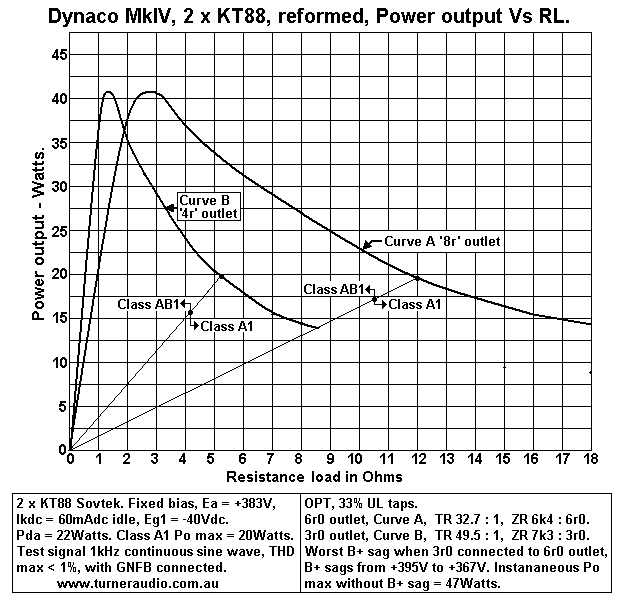
Fig 7. Graph of Power Output versus Output Load for output terminals for 6r0 and 3r0.
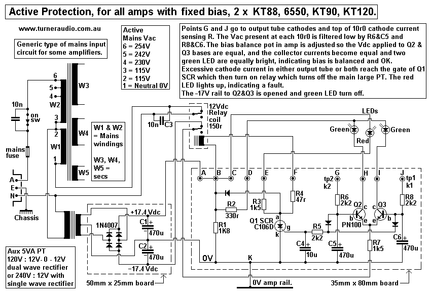
Fig 8. Schematic for active protection, bias balance indication, and usable for all amps with
a single pair of output tubes and fixed bias.

The Dynaco MkIV monobloc amp was a typical example of a 1960 amp with huge potential for
improvement. The Mark IV was rated for 40W, and its amp schematic was very similar to
half an ST70, which had 2 x 35W channels and which was better $$ value in 1960.
But many people may have had one MkIV amp for mono sound so they'd they'd just buy another MkIV,
and a new preamp with stereo to convert to stereo sound. The MkIV was first offered in 1960
and for its size and weight it offered arguably better value and performance than Quad-II or Leak
30 amps and others from 1960.
 
Fig 2.
Dynaco-mkIV-originals.jpg
Fig 2 has a pair of 1960 Dynaco MkIV monobloc amps in perfect original condition.
The original specifications are available from the wonderful website at
http://home.indy.net/~gregdunn/dynaco/components/MkIV/index.html

In case that website goes down, I repeat content of the Instructions for MkIV Kits from Dynaco :-

"The Mark IV Amplifier uses a circuit arrangement based on that of the Dynakits Mark II
and Mark III which have
become world famous for superior quality while essentially simple
and trouble free. The new 7199 tube is used as a 
pentode high gain voltage amplifier directly
coupled to a cathodyne phase inverter. All parameters are adjusted for
minimum distortion.
This type of phase inverter has the unique advantage that its operation is independent of tube
ageing
so that no adjustments are required in maintaining optimum performance.
An internal capacitive feedback loop balances
the phase inverter at the highest frequencies,
and the arrangement provides accurately balanced driving signals to the
output tubes,
which are EL-34s operated well below their maximum ratings.


The output tubes use a fixed bias arrangement which is set through use of Dyna Biaset
(patent pending) which provides
optimum linearity of the tubes and minimizes the effects of
unbalanced components. The connection of the output tubes
includes a small percentage of s
creen loading which improves the regulation of the output stage and makes it comparatively

uncritical of load impedance. The impedance match and bias conditions utilized in the output
stage provide minimum
distortion over a very wide dynamic range. In addition, 20 dB of
negative voltage feedback lowers the distortion to an
unmeasurable proportion at normal
listening levels and to less than 1% intermodulation distortion at 40W output.


The use of a minimum number of phase shifting stages along with careful transformer design
makes it possible to have
unconditional stability at both high and low frequencies.
This feature of the design means that there is no tendency toward
motorboating or oscillation
under any condition of use. The inherent linearity of the circuit, its absolute stability, and the

prefabrication of all critical wiring on the printed circuit assembly make construction completely
non-critical. The use of
conservatively operated, highest quality components insures superior and
dependable operation over a long period of time.


Specifications :-
Power Output 40W continuous, 90W peak.
IM Distortion :- Less than 1% at 40W, less than 0.05% at 1W.
Frequency Response :- ± 0.5 dB from 10 cps to 40 kc; ± 0.5 dB from 20 cps
to 20kc at 40W output.
Power Response :- 20cps to 20kc without exceeding 1% distortion within 1 dB of 40W.
Sensitivity :- 1.3Vrms input for 40W output.
Hum and Noise :- Inaudible; 90dB below 40W (choke filtering).
Damping Factor :- 15.
Output load Impedances :- 4, 8, and 16 ohms.
Tubes :- EL-34 (2), 7199, GZ-34, selenium rectifier
Finish :- Bright nickel chassis, vinyl-coated charcoal brown cover.
Special Features :- Matched tubes, Dyna Biaset for non-critical adjustment,
preamp power socket, fuse post, on-off switch.

Power Consumption :- 115W.
Size :-5" by 14" by 6-1/2" high.
Weight :- 20 pounds.
Designed by :- Ed Laurent.
Year Introduced :- 1960 Price: $59.95 kit $79.95 assembled."

I found the full kit instruction manual at http://www.the-planet.org/dynaco/Amplifier/Mark%20IV.pdf
And BTW, I guess 2 amps cost $159.90. I wonder how many weeks a bloke would have to work
before he could save enough to buy a pair of amps?

The content if Instructions quoted above is a notorious pile of self congratulatory bullshit.
But the American Dream was never perfect at any time.

Fig 3. The original 1960 amp schematic of Mk IV monoblocs.
Schem-Dynaco-MkIV-amp-1960.GIF

Fig 4. The original 1960 MkIV monobloc amp PSU.
Schem-Dynaco-MkIV-PSU-1960.GIF
Like most  PSUs in tube amplifiers made around 1960, it was designed by accountants.
The use of CLC filtering for B+ is an excellent idea, but the peanut sized choke and low uF
value electrolytic capacitors make me smile. In 1960, reliable silicon diodes were not yet available.
The MkIV chassis size was not really large enough to enable a better choke of at least 5H, with a
much higher C value for between OPT CT and 0V to bypass the CT with a low Z.

Fig 5. Revised PSU if the original PT is used...
Schem-Dynaco-MkIV-improved-PSU-2014.gif
With original PT, and if mains input = 120Vac, then HT = 400V-0-400V and without any load of
tubes the B+ will soar to +560Vdc! The original GZ34 rectifier has been deleted, and replaced with
2 pairs of series 1N5408 diodes d3-d6. The CLC filter shown could not be used with GZ34 because
peak charging currents would exceed the max rating for GZ34, causing tube failure.

I show CLC with C4+C5 and C7+C8 = modern 470uF x 350V rated elcaps. The series C will
withstand soaring B+ seconds after turn on until output tubes conduct to pull B+ down to the
idle value. 2 x series 100k 2W must be connected across EACH el-cap to equalize the Vdc
across each C.

 R1&R2 are each 50r x 20W to give approximately the same series resistance as the GZ34 tube
diodes so that the B+ remains about the same as in the original amp. Without R1&R2 the lower
internal "on" resistance of Si diodes would give B+ that is too high. The series R1&R2 also limit
charge currents to input of following CLC filter, so such currents are more unlikely to find their
way to signal path. Notice that the B+ for external preamp and input / driver stages is limited by
5 x 5W x 75V zener diodes to +380Vdc after turn on or if output tubes are removed for other tests.
I prefer using a stand alone line level integrated preamp with its own PSU
rather than deriving power from one of the power amps.

List of work to improve the PSU using the original PT :-
Remove all old electro caps and remove GZ34 and its socket.
Replace each GZ34 diode with 2 series 1N5408, (4 total for B+).
Replace selenium diode for negative bias voltage with 1x 1N5408.
Mount all diodes under chassis on additional connector strips.
Fit 4 x 470uF x 350V in a row where old elcap and GZ34 used to be.
Caps should be mounted in purpose made sheet metal box to protect stray finger
contact with cap terminals at top of caps.

SAFETY FIRST, OK!

The existing choke may be retained, even though its inductance < 2H.
R1&R2 must be added to reduce the B+ to wanted level when output tubes warm up.
R1&R2 should be each rated for 10W, and R value be determined by experiment.
How does anyone make sure they get the wanted B+ at OPT CT before using any tubes?
I use a variable dummy resistance using 20 resistors each 1k0 x 10W each.
The 20 R are first connected to make 10 parallel pairs of 2 x 1k0. The 10 pairs are connected
in series, and may be soldered in series and zig-zag pattern on a suitable 70mm x 19mm plank
of wood about 300mm long, using brass plated wood screws for the terminals.
The highest value of R = 5k0, and leads with alligator clips can change R value to
4k5, 4k0, 3k5, 3k0 etc.

Let us assume the original MkIV amp with fixed grid bias had B+ at OPT CT = +420Vdc and
the wanted Idc total for 2 x EL34 and driver tubes = 120mAdc. This would mean each EL34
would have Ea = 420V and Ia+Ig2 = 55mA each for idle Pda = 23.1 Watts which is a little high,
and Ia+Ig2 could be 50mAdc. But at least more than 40mAdc.

Assuming total Idc = 120mAdc, then the dc load after the CLC = 420V / 0.12A = 3,500r.
Solder BLACK lead between amp 0V rail and 0V end of R = 5k0. Solder one end of RED lead to
output of CLC. Use insulated alligator clip at other end and clip onto R terminal for 3,500r between
CLC and 0V. Try using 100r x 10W for each R1&R2.

Turn on amp without tubes plugged in and adjust R1 and R2 values until Vdc across
3,500r = +420Vdc. BEFORE you turn on the mains power, check caps and diodes are the right
way around for + and - voltages. With mains = 110V to 120V, make sure you have a mains fuse
= 4 Amp slow blow. BEFORE you turn on mains power, expect higher than wanted B+ voltage
and higher Idc. The Idc current in the 5k0 R may be safely measured across the first two series
500r = 1k0, so that if you measure 100Vdc, then  Idc = Vdc / R = 100V / 1,000r = 0.10Amps dc
= 100mAdc.

With dummy load disconnected, the use of a pair of EL34 or 6L6GC, KT66, or KT88, 6550
can have their bias set for 50mAdc and the B+ at OPT CT should be +420Vdc. R1&R2 will
run quite warm because Pd = I squared x R, and there are high peak currents which cannot
be easily measured with DMM. But the heat in R&R2 will be nearly the same as the anode heat
generated by GZ34, so think carefully about position of R under chassis, and keep leads long
 to soldered terminals to avoid heat melting solder over time to make a dry joint.
There is probably no need to use more than 100r for R1+R2. If B+ is still higher than wanted
with correct Idc, use a series R approximately 220r 10W between top C4+5 and the choke L1.
This added R merely drops the B+ and 100mAdc gives a drop = 22Vdc. The R value is adjusted
until wanted B+ is determined by trial. The combined choke impedance plus added R will not give
much added hum filtering but will tend to damp the series LC resonance between L1 choke
and C7+C8.

I found the Dynaco Choke = 0.9H, so Fo for resonance = 11Hz, just barely low enough to
prevent "bounce" of B+ at OPT CT between 7Hz and 15Hz.  

BIASING.
EL34 or 6CA7 require identical grid bias voltages for a given Iadc. EL34/6CA7 require a lower
Grid bias voltage than most other possible tubes such as KT88, KT90, 6550, KT66, 6L6GC, 807,
which will all require the same grid bias which is higher than that for EL34. This is ONLY valid for
where the screen Eg2 = anode Ea, as it is where UL OPTs are used or triode strapping is used,
or where pure tetrode / pentode mode is used and where Eg2 = Ea.

The 1960 circuit shows a SINGLE bias adjust pot and equal grid bias for both output tubes.
This is extremely poor practice because as tubes age they each require a different grid bias
voltage to maintain an equal anode current. Therefore there MUST be a second bias pot added
to allow grid bias voltage of each output tube to be adjusted for the same wanted Iadc.
One may add a second bias pot to allow individual biasing of each output tube.
Fig 5 above shows the re-arranged bias circuit to generate one fixed bias voltage BUT with a pot
to adjust their balance, so if one tube Idc goes low, its Idc may be increased with a turn of the pot
while the Idc of other reduced. There MUST be two 10r0 x 5W R used between each output tube
cathode and 0V to sense the Idc. There should be two external insulated terminals each connected
to each output tube cathode so that the Vdc across 10r0 can be easily measured and bias
adjustments made correctly, without guessing anything, which always causes SMOKE.

With Ikdc ( Idc between cathode and 0V, ) = 50mAdc, expect Vdc reading = 0.5Vdc. With new output
tubes, and both Vdc exceeding 0.6Vdc, then the bias circuit will need to have R14 increased so that
balance pot will give Vdc = 0.5V for both cathodes. This assumes each output tube is fairly well
matched, so that the applied bias Eg1 for each is about equal. If there is a difference of applied grid
voltage = 35%, then output tubes are un-matched, possibly faulty. The balance pot should always
allow easy balancing of Idc, and should remain stable for months after tubes warm up.

When there is not enough turn of pot to allow balance, then one or both output tubes are worn
out or faulty, or some other fault exists, like a leaky grid coupling cap. I have never seen a modern
plastic film cap short circuit or develop low resistance. But ancient paper&foil caps were notorious
for absorbing moisture and developing Idc leakage. Balancing and measuring bias condition
requires test points and the use of a voltmeter which cause confusion in amp owner's minds,
so I always preferred to instal a bias balance indicator circuit with LEDs, see further down the
page for full details.

Bias can then be balanced by thumbing a small knob on chassis top while watching for equal
brightness of 2 green LEDs, and bias condition of amp can be seen across the room and you
KNOW if there's a problem.

The added heater current for KT88 can be supplied by the original PT especially when no other
components such as radio tuners or preamps are powered via the octal output socket for power.

ALTERNATIVE TO FIXED BIAS.
Cathode bias might be possible and preferable to fixed bias when the original PT is used with
Si diodes. The replacement of GZ34 with Si diodes may allow R1&R1 or any other series R to NOT
be used. Without series R the B+ after CLC may be +450Vdc with Idc = 120mAdc.
In fixed bias amps B+ = Ea, but with cathode bias each output tube grid is biased at 0V,
and each tube has R & C in parallel between cathode and 0V. There is a positive voltage
between cathode and 0V, aka Ek, and thus grid is negative in respect to cathode.

B+ at OPT CT = Ea + Ek. ( Ea is idle Vdc between anode and cathode ).
If output tubes have Ikdc = 50mAdc, and B+ = 450V, then we might expect EL34 Ek to be about
+ 36Vdc, and the cathode Rk = 36V / 0.05A = 720r, rated for at least 7W. I don't have a reliable
formula for calculation of Rk taking in unloaded B+, PSU effective resistance after CLC, wanted
Ea, wanted Iadc and Ig2. But without a formula, you can try say 560r for both EL34, and
measurement of Ia and Ea at idle will allow calculation of total Pda = Ikdc x Ea. Suppose we
get B+ at +450V, Ek at +36V, then Ea = +414V, and if Ikdc = 50mA, then Pda per EL34 = 20.7W,
which is a comfortable Pda for EL34 which allows some initial class A Po while yielding a higher
amount of class AB Po for transients. So, the ONLY way to get the value of Rk correct is to try
Rk = 560r, and if Ikdc exceeds 55mA, and Ea becomes less than +380V, then you need a
larger value Rk, which will raise Ea and Ek, but lower Ikdc.

With cathode biasing the Rk MUST be bypassed with a LARGE value C. In 1960, 47uF was
used to bypass Rk. But input R looking into cathode = RLa / gain which can be less than 200r,
so you get a LF pole at 17Hz, too high, and likely to help cause LF instability, so minimum Ck
should be 470uF, preferably 1,000uF, and rated for at least 63V.
Use of KT88/6550 will allow higher Ikdc, maybe 60mA, because Pda rating of KT88/6550 is 42W.
HOWEVER, there is a limit and you don't want to ask too much from a 50 year old power tranny.
Hence the need for correct size mains slow blow fuse which will cope with initial large charge
currents in diodes to CLC caps and yet not give nuisance blowings. There still may be a need
for series R1&R2 between PT and diodes, perhaps less than 100r each.

With cathode bias, you'll never have to adjust anything. Bias balance is usually within 5%.
If mains voltage changes +10%, then expect higher B+, but effective Ra at dc for output tubes
= Triode Ra + ( triode µ x Rk ).
With KT88, triode Ra = 1k2, and µ = 7, if Rk = 720r, then Ra' effective Ra = 6k24, so a rise of
+50Vdc at B+ causes Ikdc increase of 8mA, and Pda will remain low enough to be safe.
With Fixed bias, Ra = 1k2, and +50Vdc causes Ikdc to increase by 41mA, and tubes will overheat.
But the bias voltage will also increase by 10% from say -38V to -41Vdc, which offsets the Ikdc
increase by about 20mAdc, so a net increase in Ikdc is more like 21mA, and Pda could indeed
be TOO HIGH. I have serviced ARC VT100 amps which should have B+ = +420Vdc, and that
is achieved with PT arranged for either 110Vrms or 220Vrms mains. In Australia, we have
250Vrms most days, so the B+ goes high and ARC become very unreliable. The cure involves
using a mains 1KVA step down tranny with 250V : 220V winding, or some other method to
reduce mains voltage.

Cathode bias bests suits class A operation because Ek will vary whenever PP output tubes
have Po exceeding the initial class A level and begin working in class AB. The possible class
A Po depends on the anode idle current; the higher the Idc, the higher the class A Po for any
load which forces the amp to work in class AB to reach clipping Po.

The load value also affects possible Class A Po. Many PP AB amps may make say
40W Class AB1 with anode to anode load = 4k0, and sec load = 4r0. With Ia = 50mAdc, the
initial Class A Po = 5Watts, not much. If the sec load is swapped for 8r0, RLa-a = 8k0 and class
A Po = 10W, and AB Po reduced to perhaps 30Watts. There's 1/3 the distortion, double the
damping factor, for free.

If a 16r0 speaker is used, RLa-a = 16k and class A Po = 20W, and Class AB Po at clipping
is 23W. It is a superb 23W!!!!
To increase Class A working, many audio-idiots will adjust fixed bias so output tubes are teetering
on edge of thermal stability. There is usually no perceived increase in fidelity, and there will soon
be a blow fuse, smokey lounge room, cooked OPT and possible PT, and an expensive bill.

I have used cathode bias in a Dynaco ST70 and included zener diodes + small Rk to limit rise
of Ek during continuous sine wave operation at levels well above the initial class A.

The best information about more better and elaborate cathode biasing is not at my page for
ST70, but for pages on 300W amps and others. Surprisingly, cathode biased amps rarely ever
move much out of class A and Ek bias voltage remains stable because music signals are not
like sine waves at clipping levels. Heavy Metal "music" is close to having no dynamic range,
thus works like a continuous sine wave plus square waves, and fidelity has no meaning.
The Best Way to get best fidelity from a class AB amp is to use a higher speaker value the
labelled outlet. If there's a 4r0 outlet, use 8r0 speakers.

INPUT TUBE HEATERS.
Fig 4 shows the 5Vac winding for original GZ34 used in a doubler rectifier to make +8Vdc
which is RC filtered for +6.3Vdc. R3 must be adjusted to get the correct +6.3Vdc depending
on the choice of input tube/s. If two 6CG7 input / driver tubes are used the approximate
R3 value = 1r5, but to get low hum at heaters the C values become unusually high at 4,700uF
and 10,000uF, but these need only be rated for 16Vdc so they are cheap, and small and able
to be fitted somewhere. The Fig 4 circuit is flexible to a certain extent if you don't want to do
all the mods. I have always used Idc heater current on at least the first input tube.
It always eliminates the possibility of hum from leakage across cathode-heater insulation.
-----------------------------------------------------------------------------------------------------
Fig 6.
Dynaco-mkIV-reformed-schem-3-may-2014.gif
Fig 6 shows the complete schematic for Dynaco MkIV pictured in Fig 1, and with a new
PT to suit Australian mains nominally 240Vac, but often 250Vac is measured. 
It has a single 310Vac HT winding for Si diode bridge. The working B+ at OPT CT is
+393Vdc with pair of KT88 output tubes using balanced fixed bias for Ikdc between 50mA
and 60mA. I had a suitable pair of C-core PTs for the job, and a future owner in Australia
will not have to use a step down mains tranny which are usually for 220V : 110V.
If our mains = 250V mains then sec = 125V, and with the 1960 PT all the secondary PT
voltages will be unacceptably high. The Vac heaters may be 6.3V with 110V mains but with
125V the heaters are 7.15V.  I started this project with two MkIV in much worse condition
than in shown in Fig 1 picture of a mint condition pair. The nickel plating over the steel
chassis was corroded on surface but responded to fine wet&dry sand-paper to remove
oxide suitable finish. The steel was easily cut and drilled for all new connections,
tag strips, cover fixing screws.

There was no need to re-paint the chassis, and corrosion is not a problem in my dry climate
away from sea air. Aluminium plates were added to cover old holes on chassis and over
area originally occupied by a printed circuit board for 7199 input/driver. The internal wiring
appeared to be the very messy efforts by a DIYer in a hurry to build a pair of kits.
Tubes were all very worn. All chassis covers were missing.
The original Dynaco MkIV amp has 4 main flaws :-
1. Input stage is triode-pentode.
2. The PSU for B+.
3. Method of biasing.
4. OPT load matching.

1. The 7199 aka 6AN8 is a mini 9 pin tube with pentode and triode within. The input pentode
is a SE common cathode voltage amp with gain > 100. It generates up to about 27Vrms to drive
the triode grid which is a concertina phase inverter ( aka "cathodyne" phase inverter.)
Open loop THD produced by the pentode at 27V is probably 3%, almost as much as THD
produced in the output stage. The triode produces two phases of up about 26Vrms to drive
output EL34 grids. The triode has to make a total of 52Vrms, but its THD is low because 50%
of the Va-k is fed back at cathode as local current FB, so expect maximum THD < 0.2%.
The overall open loop THD of the 1960 amp at 1dB below onset of clipping at 40W would
be about 4% and contain a rich array of 2H, 3H, 4H, 5H, etc. 20dB of applied GNFB will
reduce the THD to about 0.4%, or by a factor = 0.1 approx.

The THD at 1/4 full Vo or at 2.43 Watts will be approximately 0.1%. IMD with 70Hz : 5kHz
voltage ratio of 4:1 will typically be approximately 3 times the THD measured using 1kHz sine
wave, ie, about 0.3% at 2.43W. The open loop THD, IMD and bandwidth result is not as good
as using an SE triode input tube with low anode Va, followed by triode LTP with gain and which
is balanced, and which produces much less THD / IMD than any SE pentode.
Dynaco used the pentode-triode because you needed only 1 tube and one 9 pin socket, thus
reducing kit construction costs to pay for the CEO's Cadillac.

2. The original  PSU had minimal electrolytic C values and a token choke. The Vripple at 30uF
at 120mAdc = 8.8Vac, and the 0.9H choke + 20uF reduce 50Hz Vripple by factor of only 0.14 to
give 1.2Vac at OPT CT. While the amp works in class A at low levels there is good common mode
rejection of the PSU hum in B+ rail. But at higher class AB Po the Idc increase and hum increases
and is in series with each 1/2 primary so the PSU hum enters the OPT signal path and noise
at output depends on GNFB. In Fig 6, Si diodes and 470uF el-caps give noise at OPT CT
= 0.004Vac, and GNFB does not have to reduce noise. The 470uF between OPT CT and 0V
provides better anchoring of CT to 0V. At 20Hz, 20uF = 400r, and 470uF = 17r.
The resonance Fo between original choke 0.9H and 470uF =  7.7Hz, much lower than
37Hz with 20uF. The improved circuit works well in class AB. 

3. The original biasing uses one adjust pot to alter one Vdc bias voltage applied both EL34
grids but then you can get very different idle Idc in each EL34 as they age and become
un-matched, while still having years of life left . It is easy to have a net 20mAdc non-balance
of Idc flow across all OPT primary turns to create a large unwanted increase in THD/IMD.
Fig 6 shows balanced fixed bias and there is bias balance indicator circuit shown on Fig 9 below.
There is a small metal adjust knob hidden behind the two KT88 tubes. With amp turned on,
balance of Ikdc of each KT88 is easily adjusted by a finger to turn the knob in either direction
until both green LED glow equally bright. The knob works a 10k wire wound pot to balance bias.  

4. Original 1960 OPT has low ohm anode load so that if nominal speaker loads are used for
4r,8r,16r respectively, the nominal anode to anode load RLa-a = 4k3. This means the amount
of initial class A Po is less than 5W before class AB action commences to produce the 40W
maximum at clipping.

During the last 20 years audiophiles I knew preferred tube amps with low THD/IMD, extended
bandwidth, and high damping factor. The amount of initial class A before class AB begins
is more now than in 1960 when speakers generally were 4 times more sensitive, ie, they
needed 1/4 of the Po now needed for the same SPL. So instead of 1960 speakers making
94dB/W at 1Metre, they make 88dB. This is largely an accepted fact supported by the better
perceived sound quality with less sensitive speakers.

Human hearing has not changed since 1960, and more pure class A is very welcome.
With no 16r speakers around so there's no need for an output terminal labelled "16".

I found I could re-configure existing OPT sec windings beneath the bell end covers to get
the load ratio 8k4 : 8r0 or 3r5. Use of 4r0 speakers at 3r5 outlet will give good class A
performance. The original MkIV has Ea at +435Vdc and makes 40W in class AB with EL34.
Use of KT88 allowed lower Ea = +383Vdc and class AB Po is still over 40W max.
The THD results I obtained in graphs below are far better than for the original MkIV.
---------------------------------------------------------------------------------------------------------------------------
I did not want to use EL34 or the US equivalent 6CA7. The reformed PSU allows use of 
KT88 with idle Pda up to about 32W each, so Ia+Ig2 could be up to 80mAdc. This will increase
the amount of maximum possible class A1 power to about 26W if the RLa-a = 9k5 with the two
available output secondary loads either 9r0 or 4r0 at respective output terminals.
This much pure class A is more than required, and I have Pda + Pdg2 = 21.3Watts approx.
Maximum possible class A1 Po = 17W, quite enough, but requires sec loads of 13r2 or 5r8.
But with 8r0 or 3r5 at either of the two respective outlets, you get 10.3W of pure class A,
usually quite enough for most ppl, and the next 35Watts of AB Po is clean enough for
transients. Maximum class AB1 = 45W approx.

Basic data for replacement OPTs for Mk IV can be found at
http://www.triodeelectronics.com/noname.html
HOWEVER, the MkIV replacement OPT has ZR = 4,300r : 4r0, 8r0, 16r0, about same ZR as
the 1960 MkIV OPT. I assume it is impossible to re-configure secs to give higher primary RLa-a.
This means that for the best class hi-fi for most listening, ignore the 8r0 and 16r0 and only
use the 4r0 terminals, With a 6r0 speaker, RLa-a = 6k5. I do not have any idea what the
turn numbers are, how much interleaving is used or what the winding losses are or anything
else, so you might assume the replacements are no better than originals.

I removed bell end covers of original OPT to examine the connections between
sec wires from the bobbin. There were 2 windings of N turns each, and 2 of 2N turns.
This allowed me to configure the OPT differently for the Reformed Secs :-

Fig 7. Original and Reformed Dynaco Mk IV  OPT.
Original-Dynaco-Mk-IV-OPT.GIF 
Some ppl might not like the Reformed arrangement but it is for for better hi-fi at normal
listening levels with higher RLa-a for any speaker above 2r5.
The 2 speaker terminals are for nominal 8k0 : 3r3 or 7r4 and there is no need for a 16ro
terminal because the 7.4r outlet always gives enough for a 16r0 speaker, even a Quad
ESL57.
Most older 16r0 speakers have high sensitivity and just don't need more Vac than a
8r0 speaker made last month.

The OPT core Fsat will be at about 40Hz at 40W to 8k0. This is high, but at 0.4W average
listening level it is about 4Hz so although the Fsat is a bit high because its suits RLa-a 4k3,
the Fsat will never give any trouble for normal use.
The winding loss and HF response is better with the reformed arrangement.

Table 1. New Output terminal labelled 6r0 :-
New OPT outlet for nominal 6r0,
ZR = 1,075 :1, TR = 32.8 : 1 


Sec RL
4r0
6r0
8r0
12r0
16r0
Tube load RLa-a 4k3 6k5 8k6 12k9 17k2
Class of Po
aB1
AB1
Ab1
A1
A1

Table 2. New Output terminal labelled for 3r0 :-
New OPT outlet for nominal 3r0,
ZR = 2,418 : 1, TR = 49.2 : 1


Sec RL
1r5
2r0
3r0
4r0
6r0
Tube load RLa-a
3k6
4k8
7k2
9k6
14k5
Class of Po
aB1
AB1
Ab1
A1
A1
------------------------------------------------------------------------------------------------------------
OTHER THINGS DONE :-
Existing PCB with 7199 was replaced with aluminium plate with 2 x 9pin sockets for 6CG7.
New input driver amp wiring and other is all on tag strips and point to point.

I moved the 1960 15mm towards the new PT, lessening heat pick up from KT88.
The new PT with C-cores has its windings with terminals protruding into sub-chassis space.
A rectangular box made with 1.2mm welded sheet steel box was found which nicely covers
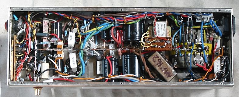
the top of the PT above the chassis. The main extra parts fitted under the chassis are
2 x 470uF, 2 x 150uF, 1 x 47uF, 1 x 5VA small mains tranny for protection circuit, protection
board, 1 x DPDT relay, plus a number of other minor parts.

The sub chassis space is quite full. I did have plans for something slightly more elaborate
but there just isn't any room.
------------------------------------------------------------------------------------------------------------
My Fig 6 schematic is nearly equal to one channel of my 5050 from 1998. Much of what I said
about the general working of the 5050 applies to the Reformed Mk IV.

With slight alteration to my basic V1, V2, V3 circuit it is possible to use :-
V1 = 12AU7 plus V2, V3 = ECC99.
V1 = 12AT7 plus V2, V3 = 12AU7 or 12BH7.
V1 = 6DJ8 plus V2, V3 = 12AU7 or 12BH7.
V1 = EF80 in triode, V3 = 12AU7 or 12BH7. 
Any changes of V1 tube type will require change to cathode biasing of V1. The other triodes
should need no change because the CCS will keep the anode Ea the same for each type.
Make sure heater voltages and pin outs are altered to suit different tubes if need be.

HF stability with Global current NFB and Global voltage NFB.
In this amp, and because the OPT does have more leakage inductance than those few with
 more interleaving, I have added some Global Current NFBwhich operates above 10kHz.
See Fig 6, L1 = 0.8uH

At 20kHz, reactance of 0.8uH = 0.1r, and this rises to about 1r0 at 200kHz. The effect of the
choke advances the phase of signals fed back at HF in addition to the effect of C12 across
R33 in the Global Voltage NFB loop. By the use of both types of GNFB, current and voltage,
the ringing on square waves at HF are much reduced and I could not get the amp to oscillate
at any HF with any pure C load between 0.05uF and 1uF.
 
No other manufacturer has ever included the current GNFB method to avoid HF oscillation,
but it works well. 
L1 choke is 5 turns of 1.2mm dia enamel winding wire around a 6mm dia ferrite tube 20mm
long normally used to increase the inductance of a short wire lead to prevent RF current flows.
The wire resistance is negligible and ZL with ferrite permeability character is negligible between
20Hz and 5kHz. But at 20kHz I found the insertion of the ferrite core into the 5 turns of the coil
increased inductance a very useful 8 times. The amp Rout < 0.8r at 6r0 outlet for 20Hz to 20kHz
but above 20kHz the Rout increases where low Ro is not wanted or needed.

The L1 choke means there is less need to use more drastic open loop gain reduction with Zobel
network R11+C5 for. 

The other critical damping stability networks are :-
LF   R12+C6,
HF  R11+C5, R33+C12, R34+C14.
Additional R+C Zobel networks across primary of OPT were not needed.

I tested the amp up to clipping with 3r0 at 3r0 outlet 6r0 at 6r0 outlet. The protection triggers
the amp to turn off if 2r0 and 4r0 are used at each outlet and with sustained clipping.

Fig 7.
THD vs Po.
Graph-Dynaco-MkIV-thd-vs-po-reformed-amp-2014.GIF
The THD was measured using 1kHz sine wave input with THD < 0.004%.
The amp output voltage was applied to a bridged T L&C notch filter to remove the 1kHz signal
and then followed by a filter to reduce the already low levels of mains related harmonics to enable
THD products between 2kHz and 10kHz to be viewed on oscilloscope and measured.
The THD % is calculated as THD % = 100% x [ THD Vrms in output signal / Output Vrms signal.]

The THD dB level is calculated as :-
THD dB = 20 x log [ THD Vrms in output signal / Output Vrms signal ]

The IMD was not measured. But if IMD is measured, you are welcome to use the common method
used in 1960 with input signal being two signal sources of say 60Hz and 7kHz, mixed together with
2 resistors to give voltage ratio of 1.0 Vrms of 60Hz and 0.25Vrms of 7kHz, thus giving the standard
4:1 ratio. The maximum IMD% occurs at the onset of clipping, while very low IMD will occur with
Po < 10W. To view the IMD, or the amount of amplitude modulation of a 7khz signal, the 60Hz
signal in the output of amp must be filtered away by a HPF of -24dB/octave below a LF cut off
pole at 2kHz. A couple of cascaded op-amp active filters each with -12dB / octave will do.

When the LF signal is filtered away, 7kHz remains plus the "intermodulation products" which will
be the sum of LF and HF and the difference of HF and LF, so you have 3 F present, 6,940Hz,
7,000Hz, 7,060Hz. The 6,940Hz and 7,060Hz are called the lower and upper side-bands.
The result of the 3 F being present and their phase relationship gives a CRO display which
shows the amplitude of 7kHz changing in amplitude at a rate of 60Hz. Where amplitude
variation is perhaps 1% of the total amplitude, it is impossible to see easily on CRO.
You would need an extremely high Q BPF to filter out each side band for measurement.
The simplest analog method for measuring IMD uses a diode+R+C detector able to measure
a low voltage of amplitude variations, and it can be based on an op-amp with suitable FB network.
The operation is very similar to op-amps used for accurate detection of the audio signals used to
modulate AM radio waves.
 
The IMD is calculated as IMD% = 100% x [ LF amplitude Vrms / 7kHz Vrms without modulation ].
The "envelope" shape of the 7kHz sine wave will suddenly become very much modulated once
the amp begins to clip. The point just below where this occurs is where maximum IMD is
observed without clipping, and is supposed to be what is quoted in data on amplifiers, although
many amp makers tell lies about this because reviewers and owners have no gear to test the
amps properly, and they wouldn't know how to use it. IMD at 1W could be less than 0.1% and
inaudible.

If you have the luxury of a spectrum analyser, and you have 60Hz plus 7kHz in the output signal,
you should see a large peak on analyser at 60Hz or 7kHz and lower level peaks at 7,060Hz and
6,940Hz. Other lower level IMD products can often be seen depending on the amount of
non-linearity of the amp. Other THD products may be seen at 120Hz, 180Hz 240hz, etc, and
14kHz, 21kHz. Mains related noise H may be seen. To understand more, read old books or
Google info about Intermodulation and Amplitude Modulation basic principles.
For ignorant non technical people, they need to only understand the terms THD and IMD,
and believe all IMD is particularly nasty sounding, and they can measure if using a good sound
card, PC, and spectral analysis program.  

With the 4:1 ratio for LF : HF, you can expect IMD to be roughly 3 times the THD for a single F
signal which has equal Vrms as the composite signal with both F present.
There is more about this in RDH4. ( Radiotron Designer's Handbook, 1955. )
Original Dynaco MkIV data does NOT include any THD or IMD graphs.
No mention is made of the exact test methods and loading conditions. Fig 7 shows the THD
being similar for both outlets with 3r0 and 6r0. The original Dynaco specs indicate
IMD < 0.05% at 1W which implies THD < 0.017%. I get THD < 0.007%. The original specs say
IMD < 1% at 40W at onset of clipping, so assume THD < 0.33%.
My amp would give about the same result when tested with lower load values at higher class
AB PO. The AB waves would have far less PSU 100Hz ripple because my PSU is so much better.
The first 10W are very important.

My amp manages THD < 0.05% at 10W, which is a good result IMHO, and I am using only
15.5dB GNFB, not the 20dB GNFB as in 1960 original amps. The THD graphs above have
logarithmic scales for THD and for output power. log scales give greater detail and better
understanding. The curves for THD are nearly straight from clipping onset down towards left
side of graph. At 2.6W and at 0.007% THD, the curves level out for lower Po. This is because
the THD% of the amp does reduce below 2.6W, but the residual PSU noise, tube noise,
oscillator signal noise and distortion remain constant, so the amp THD sinks below the noise
flaw of the amp.

After I re-configured the OPT sec windings, I used insulated bolts and fibre washers under the
nuts holding bell covers. Probably this helped to reduce iron caused distortions at low Vo levels,
sometimes seen in THD graphs as a peak on the curves at below 1 Watt level, usually not
exceeding 0.05%. But there is no such peak at low level in my graphs.
I conclude that the GOSS E&I core material made in the USA in 1950s for OPT was very good.

Fig 8. Po vs RLa-a, at THD < 1%.
Graph-Dynaco-MkIV-Po-vs-outputRL-2014.GIF
Fig 8 shows the maximum output power with 1kHz sine wave measured at each of
the two output load selections, and where THD < 1%, with GNFB connected.
Curve A is for Com-to-6r0, and Curve B is for Com-3r0.
The Pda at idle for each KT88 is 20Watts, and maximum class A1 is 17W, achieved
with 13r9 connected to 6r0 outlet and 6r0 connected to 3r0 outlet. If the idle Pda of
each KT88 was raised to a safe maximum of 32W, then Ea would be +385Vdc,
and Ia = 83mAdc. 25Watts of pure class A1 max is then available with lower load
values but the betterment of audio fidelity probably cannot be discerned.
The class AB1 operation will sound just fine.
-------------------------------------------------------------------------------------------------------------
Active protection is used to stop runaway Idc in output tubes which might damage
an existing precious OPT before any fuse blows. The bias is balanced by VR1 and
when the Idc in each output tube is very close to being equal, both green LED will
glow equally brightly. If the Idc balance changes by more than 4%, the LED brightness
will differ and be easily seen. Green LED brightness may vary during warm up.
But after 10 minutes and after careful adjustment of VR1, the brightness can be
made equal and Idc in each tube is equalized and biasing is OK.
Fig 9.
Schem-Protection-reformed-Dynaco-MkIV.gif
Fig 9 is as simple as I could make for the bias balance indicator and active protection.
The content within the dashed line rectangle with terminals A to K is on a 3mm thick
circuit board 35mm x 80mm, and carefully mounted so it can be removed by undoing
one M3 nut and swung away from amp on flexible leads to allow inspection and maintenance.
The two green LED are 5mm dia and mounted 18mm apart on front panel just above the
mains rocker type on-off mains switch.

There is one red LED between the two green.
The green LED indicate the amp is turned on, and the bias balance condition.
Any bias problem will make one of the two LED go out, instantly telling the owner there is
a problem, and he can see it from across the room. If either output tube conducts more than
about 3 times the normal cathode idle Idc for longer than a few seconds, the Q1 SCR will
latch on, turning on the relay which opens the Mains Neutral line to the large PT thus turning
off the amp internally and automatically.

The relay also opens the negative -17Vdc rail to Q2, Q3, thus turning off the current in
green LED so they go out.

The relay also turns on the red LED which immediately tells the owner there is a problem.
The amp may re re-set by turning off the mains switch, waiting 3 seconds, then turning amp
back on. If the amp turns off internally again and without any signal, there is a problem which
needs a service person.

The excessive Ikdc can flow in either output tube for a variety of reasons :-
1. Spontaneous output tube failure because air enters tube after glass to metal seals break down.
2. Tubes have become so old the gettering fails and tube becomes gassy, and conducts more Idc.
3. Owner has connected shorted speaker cables.
4. Speaker has jammed voice coil or short circuit with very lower Z.
5. ESL speaker has arcing panel.
6. Coupling caps to KT88 grids have failed to a short circuit.
7. OPT has developed shorted turns.
8. Some idiot has volume level way too high and speaker Z too low, ie, has connected 3 ohm
speaker to 6 ohm outlet, and is intent on deafening everyone.
9. Irate Ex-Wife gets even by using hammer to "adjust the bias."
10. Teenagers are in control of dad's old Hi-Fi system at end of school year party.

View of underside of re-engineered Dynaco MkIV....
Dynaco-MkIV-reformed-5-under-chassis-feb2015.jpg

When all the tubes are happy with their currents and dance with the voltages, there should
be the finest music in the air - Patrick, 2015.

To re-engineered Dynaco ST70
Back to Re-engineered amplifiers
Back to Education and DIY directory
Back to Index