MING-DA 80W PP with 845
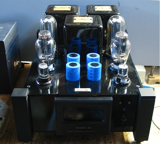
Picture 1. Ming Da, made about 1996, re-engineered 2011.
Picture 2. View under chassis after re-wiring amp.
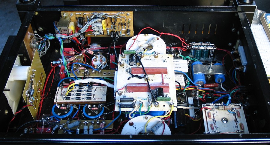
The original circuitry had many parts such as the diode arrays
hanging on "mid air wiring",
a common bad practice in China where use of good boards or
terminal strips is avoided to
save expense.
Many circuit connections were done using 4mm brass spacers with
nuts and lugs, so there
were many non-soldered connections which would give trouble in
future.
I gutted everything in both amps, but left in useful connector
strips with brass connectors
which I soldered up so no connections could come loose or suffer
corrosion.
All resistors were replaced where more than 150Vdc was present
because a couple had
gone open, and one had shorted resulting in Vdc across 3 of 4
series electros being much
too high. Chinese resistors of 1990s were not reliable. The
Chinese communist party
runs the industry in China and sometimes includes fire crackers
in its products, but you
don't know where they are, or when they will explode, and
sometimes things just stop working.
The Taiwanese metal film R I have used are much more reliable.
The 845 have B+ = +1,200Vdc. There is a CRC B+ filter using
117uF - 100r - 117uF.
The Vripple at OPT CT = 0.3Vac. To make up each 117uF, 4 x
470uF/450V are used in
series with 220k across each. The 470uF were retained because
they appear to be reliable,
and ripple current is very low. I retained the use of Si
rectifiers throughout. For +1,200Vdc,
I used a bridge using 12 x 1N5408 with diodes mounted on a
board, and all painted with
varnish to stop effects of moisture.
I worked out what voltages were available from existing two PTs
and the properties of OPT.
Then I built a much better circuit of my own with all soldered
connections and boards placed
to make all connections and parts and service measurements
accessible. I removed all 4
existing biasing pots which ridiculously awkward for anyone to
adjust and get right.
Two were for 300B, but they actually did nothing.
The board at top left is for active protection and 845 Ikdc
balance indicator amp.
Fig 1. Reformed Ming-Da schematic.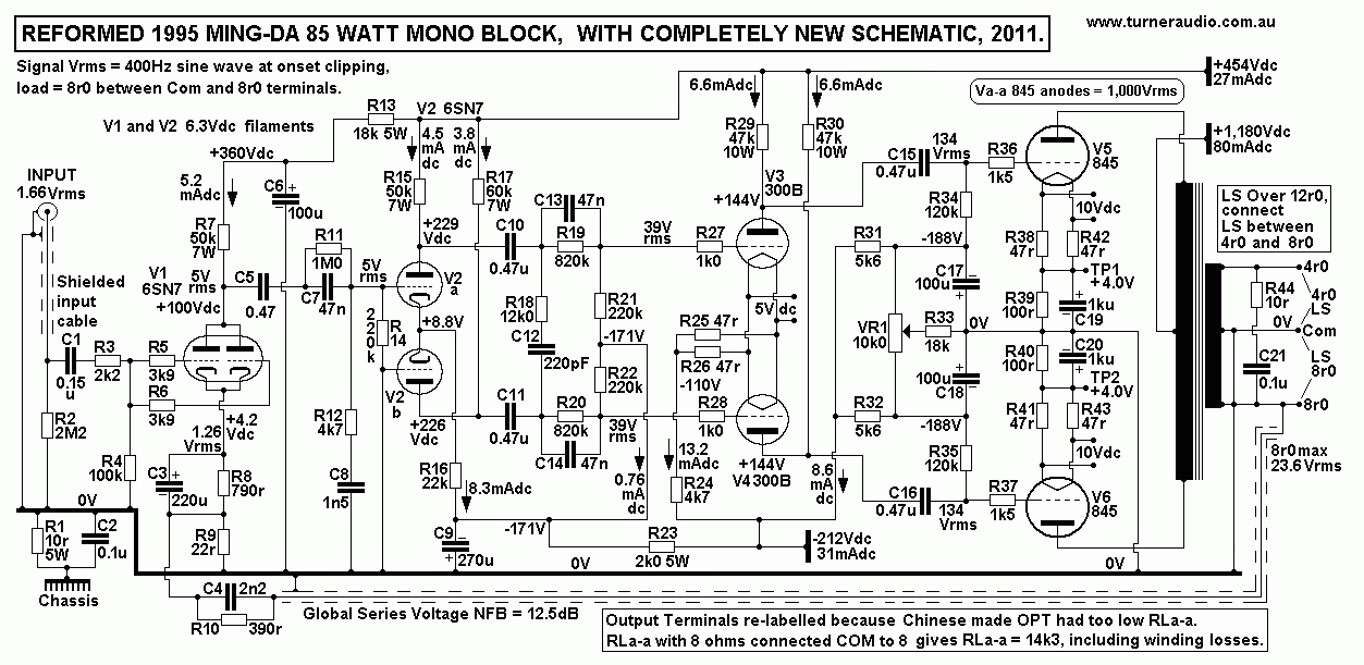
Listeners here gathered around "The Mingies" when I had them
reformed. Music was what everyone expects from a good triode amp
- just fabulous.
The OPT quality was poor by my standards. The turn ratios were
all wrong. Used with original labelled loads, the amps would
soon cook the 845
to death if high levels were used. Distortion, noise, and Rout
were all way too high, and bandwidth and stability bad.
The original OPTs had 3 output terminals meant for common, 4r
and 8r. If 4r speakers or 8r speakers were used where intended,
the anode loading
RLa-a becomes way too low at about 8k0, when for best operation
it should be never lower than 19k0, where Ea is a high 1,200Vdc.
So what went
wrong in Chinese minds during design? Quite a lot, it seems.
So I re-arranged the labels on OPT so 8r speakers are used
across originally labelled 4r portion of OPT sec winding, 4r
speakers are used on
winding portion between 4r and 8r, and 16r speakers are used
across whole OPT sec. This means the RLa-a is doubled, and THD
is more than
halved, Rout is halved, and tubes won't cook.
Graph 1. Ra curves for original 845.
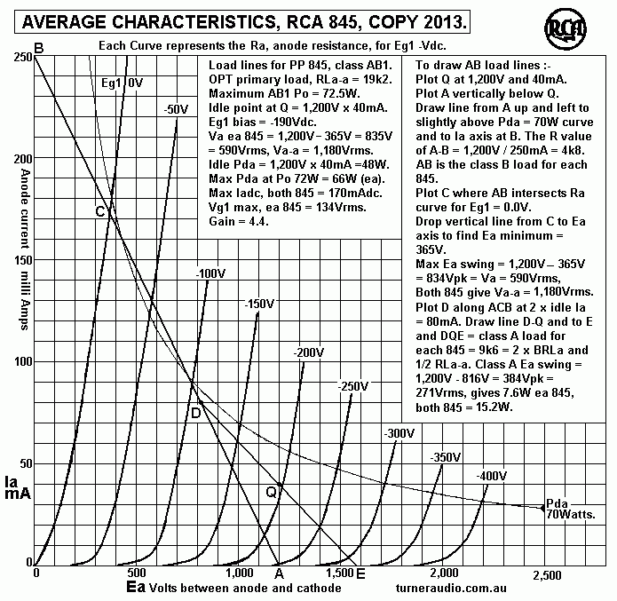
Graph 1 shows 845 Ra curves with the PP load lines drawn for Ea
= 1,200V.
The minimum RLa-a which I would ever use for Ea = 1,200Vdc =
19k0. You then get
72W of Class AB1 at anodes of 845, and if OPT winding resistance
losses = 7%, you get
say 67W at secondary terminals at clipping. The amount of
initial class A1 Po depends on
the signal Ia change never being greater than +/- the idle
current Idc. In this case where Ia
at idle = 40madc, the signal Ia for class A changes up to 80mA
and down to 0.0mA, ie,
+/- 40 mA pk. The Irms value = 40 x 0.707 = 28.3mArms. This is
the maximum class A Iac
change in the RLa-a for the two tubes, so Class A Po = RLa-a x
Ia squared
= 19,000 x 0.0283 x 0.0283 = 14.9W.
The straight line ADCB is the class B load for each 845, and has
a value of 0.25 x RLa-a
= 4k75. The straight line EQD is the class A load of each 845,
and has a value of 0.5 x RLa-a
= 9k5.
The lower RLa-a becomes, the lower the class B RLa load ohms,
and higher the maximum Ia,
and % of class A working becomes lower.
Now the reformed Ming-Da produced 70W at 8r0 load so anodes
would make 75W,
but there is a slight drop in B+ because of increased Iadc
across PSU resistance.
The reformed amp has RLa-a = 14k, and includes total P&S
winding resistances of maybe 1k0,
so winding losses are just over 7%. The RLa-a of 14k0 is a bit
too low. But my schematic shows
the 8r0 used across what was labelled for 4r0 originally.
If 4r0 speakers are used on these amps using original labelled
Com - 4r0 terminals,
RLa-a becomes 7k5 including Rw of 1k0 so winding losses = 13.3%.
RLa-a = 7k5 gives B RLa of
1k87 and Ia peak = 0.31A. Pda due to signal current will be
about 117W, and tubes will over
heat with continuous sine waves at high levels. The B RLa is
lower than the 845 Ra of about 2k2.
Max Po for 7k5 at anodes = 88W, and at output terminals = 76W.
Class A Po = 5.2W, and while working in mainly class B the DF is
less than 1.
The point I make is that there's nothing to gain by using a
lower RLa-a below 19k0.
Using higher RLa-a will give more pure class A working, lower
THD, higher damping factor,
lower OPT winding losses and wider bandwidth. This always gives
better sound.
With Ia = 40mAdc at idle, each 845 idles with Pda at a
comfortable 48W.
Their rating is for 100W, but only a fool would idle any 845 at
100W, and 70W is what I
consider maximum safe level, and where only class A is wanted.
But sooner or later, someone
will connect low Z speakers to the wrong output terminals and
this will overheat the already
fairly hot 845 at high levels.
If the reformed Ming-D are to work in pure class A only, their
RLa-a must be 51k!
But you get a very nice 41W. But for pure class A with 4r0, the
OPT should have a highest
available ratio = 51k : 4, ZR = 12,750:1, with TR = 112.9:1.
But the existing OPT has 13k : 4r for its highest ZR and turn
ratio, Com to 4r0. If pure class
A was wanted, the lowest speaker load usable = 15.6r.
So these Ming-Da cannot provide best class A performance unless
you have 16r0 speakers.
One might be tempted to increase the Ia for 845 to 58mAdc to
have idle Pda = 70W.
Then RLa-a is 33k0. Then the speaker load for pure class used
between 4r & 8r terminals
needs to be 10r0. So using more idle current hardly improves
anything, and just wastes
electricity.
The amps sounded fabulous as I have made them. Average levels
for most listeners is
less than 1W per channel, with peaks perhaps reaching 30W. This
amp will cope brilliantly.
The amp makes at least an initial 10W before AB action
commences. The crossover to class
AB with all triode amps is usually completely tolerable because
the cut off behaviour is gradual
and not many harsh sounding harmonics are produced, so class AB
with 845 sounds better
than say a pair of KT88 in ULAB1 mode.
And who would think 300B work well as drivers with only 6.6mAdc
of anode Idc?
The total RLa for each 300B = 39k, and with Va = 134Vrms, the Ia
change = 4.8mApk.
This is OK because it is safely less than 6.6mAdc of idle Ia.
Originally, the 300B stage had
about 4mAdc in each 300B and it was the first stage to clip, and
THD was high.
Biasing was all done incorrectly, with two bias pots having
little effect. The low Iadc in each
300B allow them to not need Iadc to be balanced, and the common
Rk R24, 4k7 regulates
the Ia of both 300B very well, and with such low Iadc, the 300B
run very cool and should last
50 years. So I was able to delete the two bias pots Ming-Da
used.
300B work well to make 134Vrms max at each 845 grid. It would
have been better to use a
choke with CT for balanced choke feed to 300B anodes, and with
series R between ends
of choke winding and anodes. This would allow about 20mAdc in
300B which would mean
less THD. But as is shown, the 300B work with B+ between -110Vdc
and +454Vdc, and Ea
= +254Vdc. The low Ra of 300B allows a max Ea swing of +/-
230Vpk giving 165Vrms max!
The output 845 have fixed bias and Iadc at only 40mA which is
simply balanced by a
VR1 10k, 3W wire wound. Should anyone build the amp shown, they
could change R33 to
12k0, and put a VR2 10k linear wire wound pot in series to 0V so
the total Iadc for both 845
can be adjusted to equal 80mAdc. I have found this to not always
be necessary. If one 845
Ia goes up to say +60mAdc, while the other is at 40mAdc, the VR1
should be able to reduce
the higher Ia and increase the lower Ia so they are equal at
about 50mA each.
This is quite acceptable. If Ia of one or both 845 go higher
than about 100mAdc, then the
protection circuit will turn off the amp.
Chinese Tangin 845 were tried, and all 845 in both amps arced
over with Ea at over 1,100Vdc.
I built a breadboard test circuit. These 845 arced over
internally with B+ only +800Vdc.
The owner didn't get a refund, and was most disappointed. The
internal appearance of these
crap tubes showed flimsy construction compared to the Shuguang
B, which I think are best,
IMHO.
The amp is fitted with 2 yellow Leds to indicate bias balance,
one blue LED for 'on' = OK,
and one red Led for "NOT OK" when the amp is turned off if the
845 conduct too much Iadc.
The 845 idle Iadc = 40mAdc, so idle Pda = 47W, so they always
run cool. The Iadc is easily
balanced by turning the head small black metal knob at front of
amp which adjusts VR1 pot.
This means the owner never has to remove these very heavy amps
from their hi-fi stand,
then turn the amp upside down on carpet and remove a cover, then
fiddle around adjusting
pots and probe around circuitry with volt-meter leads with
lethal Vdc present. Its now 2014,
and its been 3 years since I reformed the Ming-Da and the owner
has had no problems.
Should anyone try to build a new PP class AB amp with 845, they
may find it a big challenge.
Here is a sample of what I might do if I made a new amp with PP
845 :-
Fig 2.
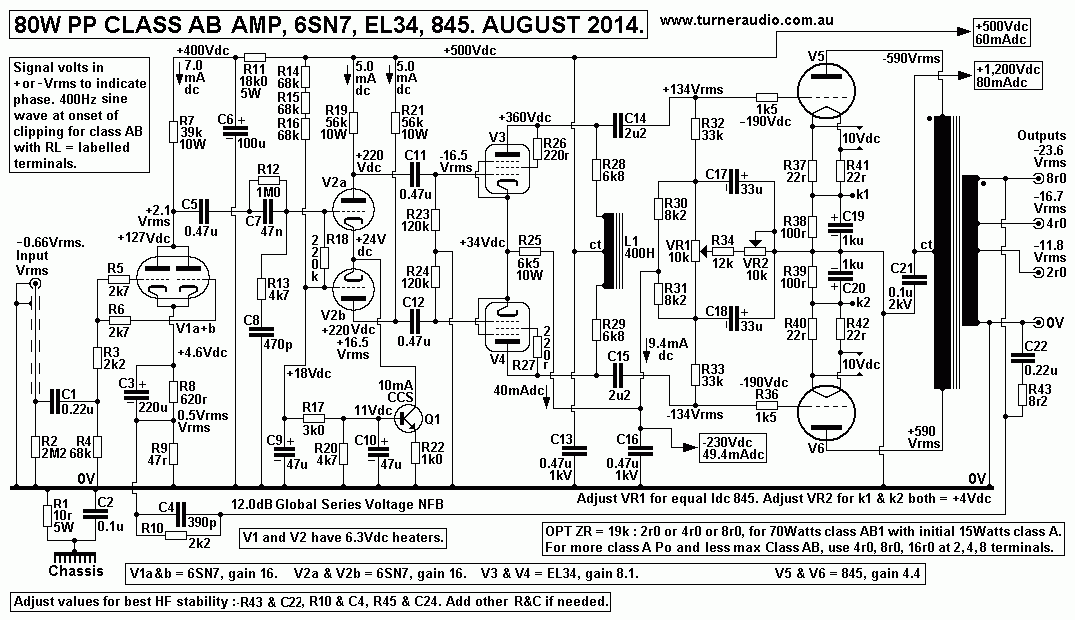
Fig 2 shows a similar schematic to Ming-Da, with 4 tube stages
but with different OPT,
19k : 2r, 4r, 8r, and EL34 triode driver stage with Choke Feed
and CCS for V2 LTP.
The B+ rail voltages and general schematic has been rationalized
to benefit music,
not benefit anyone's profit margin. No doubt nobody will try to
build this amp, it is too difficult.
Fixed bias is used with adjustments for both Idc balance and the
overall level of Idc for both tubes.
A protection circuit is wise, because there are some 845 being
produced now (2014) which
may not last very long. The use of two EL34 in triode, each with
idle Ia = 20mAdc, makes an
excellent balanced amp driver stage with maximum possible Va-a =
360Vrms, and THD < 1%.
The choke L1 is wound using about 5,000 turns 0.2mmCu dia wire
on 25T GOSS E&I core
with stack 32mm, and it has a CT, and no air gap. L1 functions
acts like the primary inductance
of an OPT to give very high reactance between 20Hz and 20kHz.
The resistance loading of
EL34 by choke is negligible between 20Hz and 20kHz. R28 &
R29 prevent the choke shunt
C and its shunt inductance from being directly connected to EL34
anodes at extreme F outside
the F band so the EL34 gain remains at least 7 even outside the
AF band and phase shift by C&L
shunting is avoided. The dominant load on each EL34 anode are
R32 & R32, 33k. This RLa of
33k = 25 x Ra of EL34 so that voltage gain approaches µ. Peak Ia
swing at 134Vrms = 5.6mApk,
which is much less than Ia = 20mAdc, and you can expect THD <
0.3%, mainly 3H, and declining
to say 0.03% at 13.4Vrms at typical listening levels.
The pair of EL34 require 33Vrms grid to grid for amp clipping.
The 6SN7 input stage and
following 6SN7 LTP both have gain of about 16, so the total gain
= 256. So therefore about
0.13Vrms is needed at V1 Vg-k for clipping. The global NFB
voltage applied to V1 cathode
= 0.5Vrms, so input for clipping is about 0.66Vrms.
To get more class A with lower class AB, a 4ohm speaker may be
plugged in between 0V
and 2r0 labelled outlet. This doubles the Class AB RLa-a from
19k0 to 38k0. With RLa-a
= 38k0, the initial class A increases to 30W, with about 47W
maximum class AB.
The Ra-a at 40mA = 2k7 + 2k7 = 5k4 and if RLa-a = 38k, then
damping factor without any
GNFB = 38k0 / 5k4 = 7.0, and this could be the highest DF
possible for any power triode.
Rout at 2r0 ohm outlet = 5k4 / 9500 = 0.57r. Winding resistance
may raise this to say 0.6r,
and with 4r0 load the DF = 4 / 0.6 = 6.7, quite acceptable.
GNFB need not be used. Then V1 could be eliminated. About 2Vrms
is needed at V2a grid
for clipping while V2b grid is grounded.
For slightly better PP pure class A operation, the Ea for 845
may be reduced from
+1,200Vdc to +1,050V as shown in my page for single ended 845 at
monobloc845se55.html
The parallel pair of SE 845 produce 55Watts of pure class A with
OPT primary RLa = 6k0.
Each 845 has RLa = 12k0, and with the same pair used in a PP amp
you can expect the
same 55W with OPT RLa-a = 24k0. There is a slight amount of grid
current draw above
50W, so 55W will actually be slightly Class A2.
Fig 3.
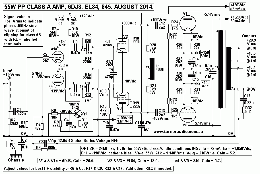
Fig 3 shows a simpler amp than Fig 2 or the Fig 1 reformed Ming
Da. Fig 3 has operating
conditions for pure class A :-
Ea = 1,050Vdc, Ia = 72mAdc, Eg1 = -155Vdc, idle Pda each 845 =
75.6W.
For Po 55W, Va-a = 1,148Vrms, and Vg-g = 218Vrms, ie, 109Vrms at
each 845 grid.
The use of EL84 in triode for the V2 &V3 balanced amp driver
gives very similar operation to
EL34 with nearly same Ea and Ia conditions, only the EL84 gives
more than twice the gain
of EL34. This means the gain required by an input stage need
only be about 26, and use
of 12dB GNFB will give Vin sensitivity of 1.8Vrms for clipping.
The best V1 tube I can think
of is 6DJ8, which has to only produce 6Vrms to drive EL84. The
V1a & V1b are in an LTP
so its a balanced amp with very low THD. I show Input to V1a
grid and GNFB to V2b grid.
You will find the arrangement functions excellently and gives
good sound. For operation
without GNFB, just disconnect R6 & C3 from top of R4. and
47r then grounds V1b grid.
The input for clipping with no GNFB = 0.46Vrms.
V1 6DJ8 could be replaced with 6CG7 without any changes to the
Fig3 schematic.
Because there is a cathode CCS the Iadc for V1a & V1b will
remain constant and anode
Ea will also remain constant and the 6CG7 will work perfectly
with no change to pin out or
to any R values, although 6DJ8 require less heater current. But
6CG7 gain will be about
16, and this means V1 Vg-g = 0.74Vrms instead of 0.45Vrms needed
by 6DJ8 for clipping.
The drop in gain means the amount of applied GNFB is reduced
from 12dB to say 9dB,
but that's enough, and because its a class A triode amp the
sound will be fabulous.
The input with GNFB will be about 2.1Vrms with 6CG7. Some people
have told me that 6CG7
sound better than 6DJ8, and to avoid controversy, I always
agree.
I should talk about 845 ! In 2008, the SE55 amps I
made used KR Audio 845, but I found
much cheaper Shuguang type B were just as good sounding and far
cheaper.
There are some very interesting comments about anode and cathode
materials at
http://www.emissionlabs.com/html/products/Warning-Chinese-Fake-mesh.htm
The use of carbon anodes is discussed, and from what I read,
only high temperature bright
emitter thoriated tungsten filaments should be used with carbon
anodes, because of carbon
evaporation within the tube. This carbon settles on inside of
glass tube. Higher efficiency barium
oxide cathodes like those in a 5U4 or a 300B have been tried in
several versions of 845 including
KR Audio, and their dull red color averages 777 degrees C. See
page 2, RDH4.
Temperatures of +/- 10% make tubes unreliable, with shorter
life. Such low temperature oxide
coated cathodes are prone to positive ion bombardment where
electrons are knocked off a gas
molecule to leave it positively charged and the the heavy gas
molecule rushes towards negative
cathode at high enough speed to damage oxide coating. Ea should
be kept below +900V to
avoid ion bombardment. The higher the Ea, the higher is the
positive ion speed.
I don't believe all I read at websites. Emission Labs
say its impossible to get a good
electrical connection from wire leads to carbon anode, which is
brittle, so a tensioned rivet
is needed, but that this can cause small cracks from movement
during shipping. But then
carbon plates have been around a very long time and I've never
read anything bad about
845 and many other carbon anode tubes in OLD BOOKS written
before 1960.
Emission Labs rave on about their metal MESH anodes being better
than "punched metal"
used by Chinese and cite the woven mesh does not give rise to
microphony compared to
Chinese tubes. Well, I ask then why are nearly all DH tubes
microphonic no matter what the
anode material? The anode in fact does not vibrate very much
like a bell to any great extent.
But the cathode wire plus grid wires are flimsy and flexible in
most DH tubes and do move
move when the tube vibrated.
If you tap a 300B with a finger, you hear a ding-ding from the
tube itself because of cathode
and grid wires move to change cathode to grid distance which
modulates the electron stream
so you get ding-ding at the speaker. If there is 12dB GNFB, this
noise by tapping tube is reduced
-12dB.
But sound from speakers usually is not enough to cause
significant microphonic effects
greater than other phenomena such as THD, IMD, and emission
noise.
So, here I am in 2014, and I might bravely say the Shuguang type
B 845 is still the best you
might buy. I do not accept that each time someone launches a new
845 on a fickle market
it means that 845 is better than anything produced since 1930. A
recent maker ELROG in
Germany has started making 845, $1,000 a pair, and my advice is
to stay with Shuguang B
for a couple of years to see if there's a flaw in ELROG
reliability.
Usually many boutique tube makers will never admit to their tube
failures.
The OPT with 24k0 anode winding must be extremely carefully
wound for low shunt C and
with very good insulation. Sec outputs should be for for 3r0,
6r0, and 12r0, so TR = 89:1,
62.5:1, 44.5:1. The OPT must have total winding losses in class
A1 of less than 5% so that
if class AB is used for a lower minimum RLa-a of 15k,
winding losses do not exceed 5%.
How did grandfather use 845 in 1935? I think he was 25 years
old. He may have used a
pair of 2A3 to drive a 1:2 step up IST between 2A3 and 845, so
2A3 would have produced
109Va-a, or 54.5Vrms at each anode, and 13.6Vrms at each 2A3
grid. The input stage might
have been a single smaller triode, 6J5, with IST with 1: step up
so its anode Va = 13.5Vrms,
and its input would be about 0.9Vrms. With so many transformers
of questionable quality,
perhaps he got bandwidth of 80Hz to 7kHz if he was lucky. The
use of GNFB would have
been impossible because of phase shift. But within 12 years a Mr
D.T.N Williamson taught
the world how to make better OPTs and how to get rid of ISTs and
how to get noise and
distortion down to acceptable levels using moderate amounts of
GNFB.
Be my guest if you want ONLY real DH triodes in your amp, and
without GNFB. Expect huge
problems with hums and microphony and difficulties with biasing
etc. Expect high THD and
IMD, and remember, in 1935, the best OPTs and ISTs were quite
primitively designed and E&I
laminations generated as much THD or more than did the tubes.
The use of GOSS cores, and the more modern driver tubes
including pentodes strapped in
triode, plus better filtering of B+ supplies all do less awful
things to music than grandfather's
efforts.
Rear end of Ming-Da amp.
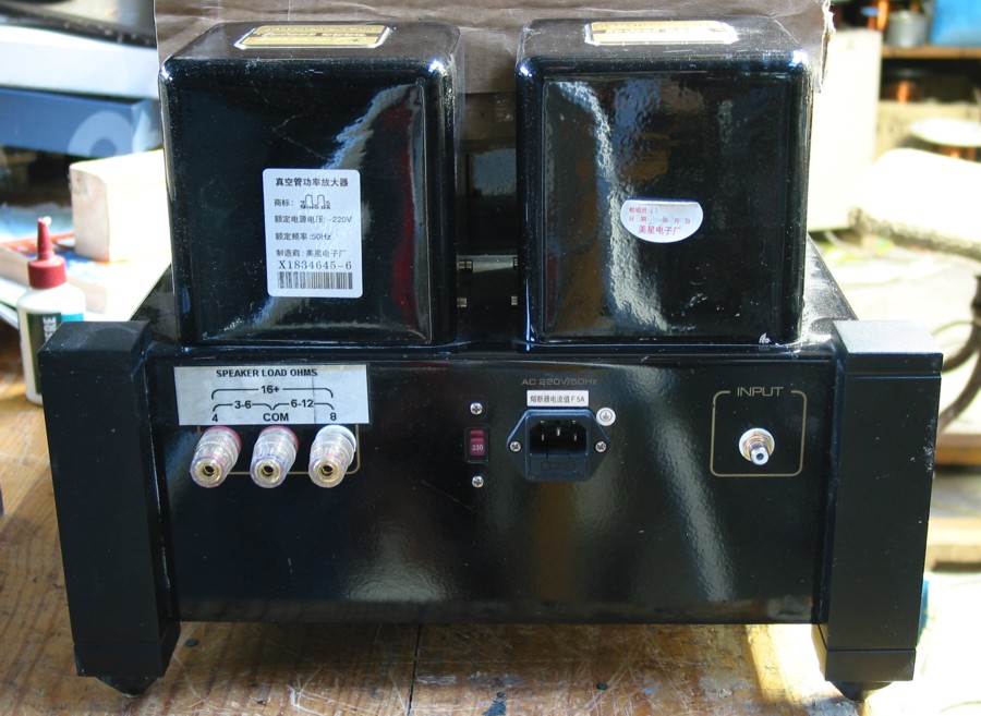
Notice the TWO PTs side by side. If Ming-Da really wanted to
make a good amp,
they would have used just ONE good big PT. Notice the Chinese
writing on labels at rear
of amp. Notice the left Chinese label which has "220V" written.
But we have 255Vac some days. The working voltages I show on my
reformed are with about
250Vac mains. I don't what would happen if mains was 220V, I
guess all Vdc rails would reduce
by 15%, so instead of 1,200Vdc B+ it would be +1,056Vdc. I found
heater voltages slightly high,
and with 220V maybe they'd be slightly low. I biased the
845 for only 40mAdc to avoid
overheating, especially with the original OPT strappings which
has the RLa-a much too low.
re-engineered amps directory
Index page