OTL amps, 6AS7, 6C33c, December 2013.

Updated April 2016.

This page is about OTL amps, strengths and weaknesses, and why not having an output
transformer may ruin good music. I discuss why why you need so many tubes such as 6AS7, 6336,
6C33c triodes in any OTL amp to suit today's speakers with low impedance and low sensitivity.

I give reasons why an external add on "speaker matching transformer" is the only item which can be
purchased "off the shelf" from small manufacturers, and why these items will make an OTL amp give
less THD/IMD, higher damping factor and excellent bandwidth and better music.

I explain what amps can be built using 6AS7, 6C33c and with a suitable well designed OPT.
Such work does require a high amount of skill, patience, tools, time and knowledge.

Contents :-
Strength and weakness with OTL amps and 3 basic remedies for negatives.
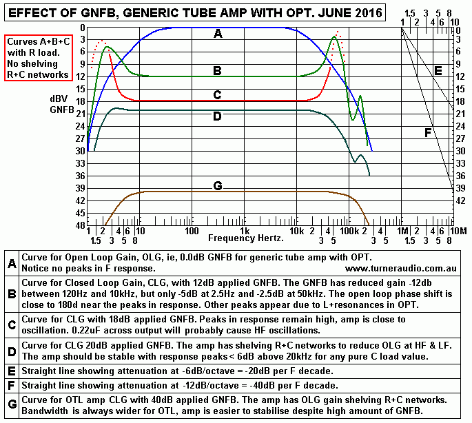
Fig 1. Effects of using NFB in tube amps.
Explanations for need to respect Bode and Nyquist issues regarding phase shift, gain, and NFB.
Tables 1, 2, 3, 4, 5,
Helps to explain use of mains toroidal PT as a speaker matching transformer SMT or for OPT.
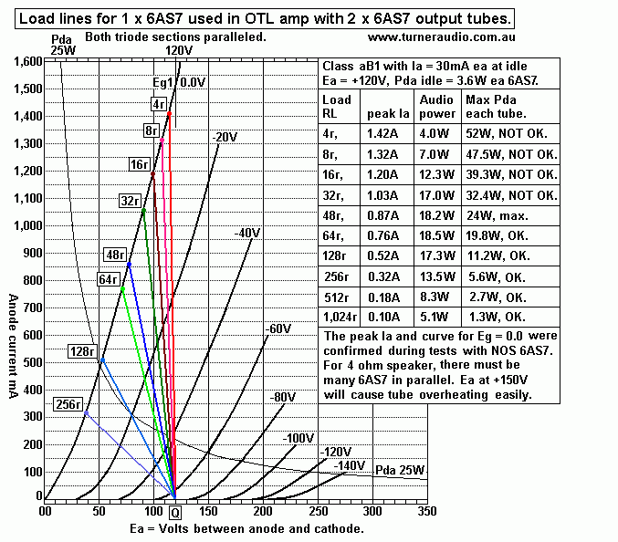
Fig 2. Graph of loadlines for one of a pair of 6AS7, for 4r,8r,16r,32r,64r,128r, 256r,
Includes table for Po and Pda.
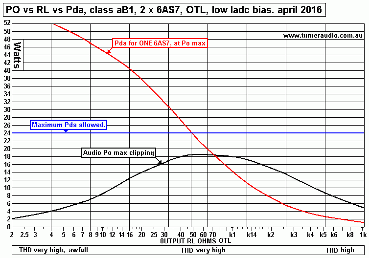
Fig 3. Po vs Pda for low bias class aB1 for pair 6AS7, RL from 2r0 to 1k0.
Calculating Pda for any level of operation.
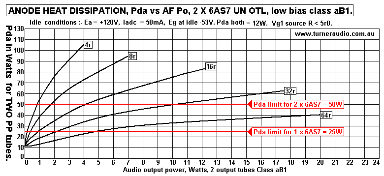
Fig 4. 5 graphs for Pda vs Po for 2 x 6AS7 OTL with 4r,8r,16r,32r,64r.
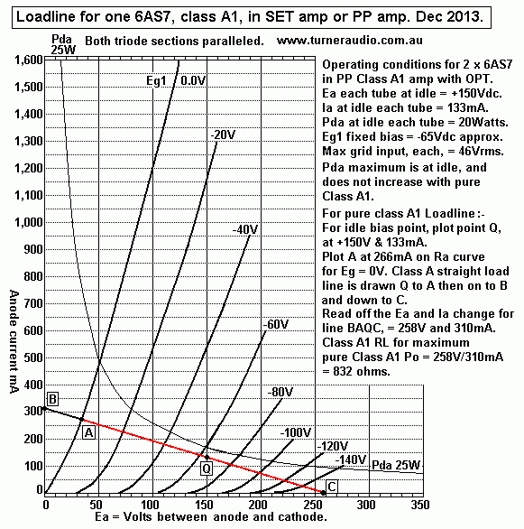
Fig 5. Class A1 loadline for 832r for 1 x 6AS7.
Notes on class A1 use of 6AS7 - with OPT.
Table 6. About class A1 operation of multiple 6AS7 and 6C33c.
Fig 6. Graph for loadlines, Class AB1 with 2 x 6AS7, A RLa 400r, B RLa 200r.
Table 7. About normal PP with OPT with CT.
Table 8. About Series Pair with external OPT or SMT.
Properties of toroidal SMT from http://www.zeroimpedance.com
About use of 6C33c.
Fig 7. Graph of Class B 4r0 loadlines with Ea +80V, +120V, +150V.
Class A with 6C33c.
Fig 8. Graph of class A loadline 382r for 1 x 6C33c.
Calculating THD, RLa and Po.
Table 9. About SET 6C33c, Ea, Ia RLa, Po.
Table 10. About more configurations Ea, Ia, RLa.
Class AB1 6C33c.
Fig 9. Graph for 3 class B RLa, 57r, 94r, 175r.
Fig 10. Graph for AB1 loadlines, A RLa 350r, B RLa 175r.
Fig 11. Schematics - basic output configurations no1, 2, 3.
Fig 12. Schematic Basic Series Pair + CFB with OPT.
Fig 13. Schematic Basic Series Pair OTL with CT choke and CFB.
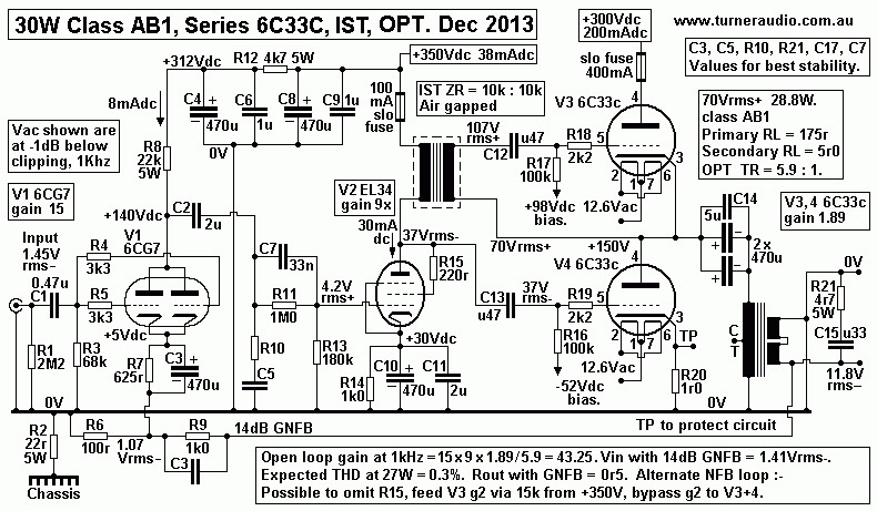
Fig 14. Schematic 30W AB1 Series Pair 6C33c + OPT + IST .
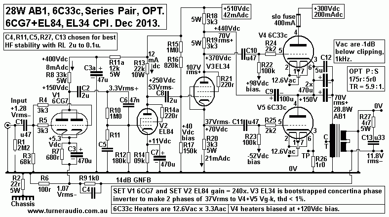
Fig 15. Schematic 30W AB1 Series Pair + bootstrapped CPI, Futterman.
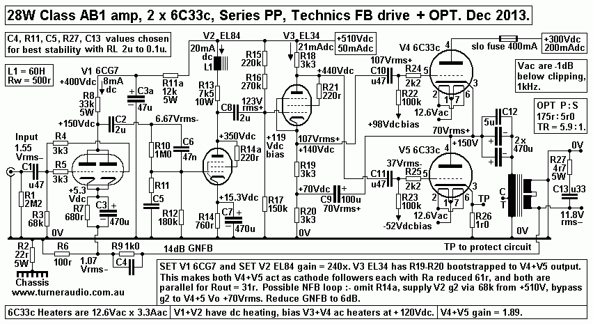
Fig 16. Schematic 30W AB1 Series Pair + bootstrapped CPI + Technics local FB.
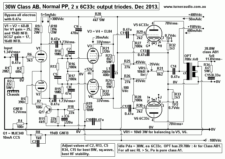
Fig 17. Schematic 30W AB1 Conventional PP with CT, balanced drive, OPT.
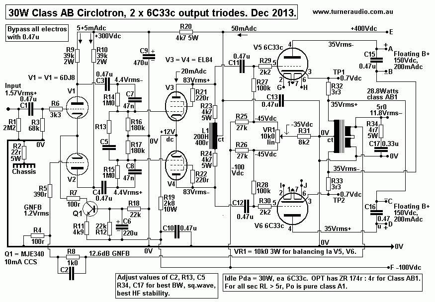
Fig 18. Schematic 30W AB1 Circlotron + OPT.
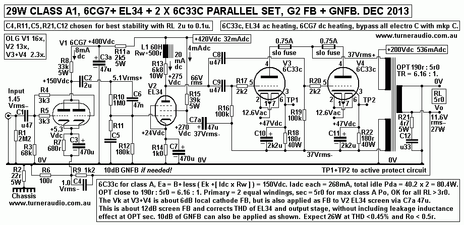
Fig 19. Schematic 29W SET 2 x 6C33c, screen FB to EL34, CFB, GNFB.
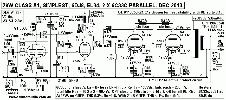
Fig 20. Schematic 29W SET Simple SE circuit, GNFB from OPT to input 6DJ8.
Table 11. Compared various numbers of 6C33c, 6AS7, Po, RL etc.
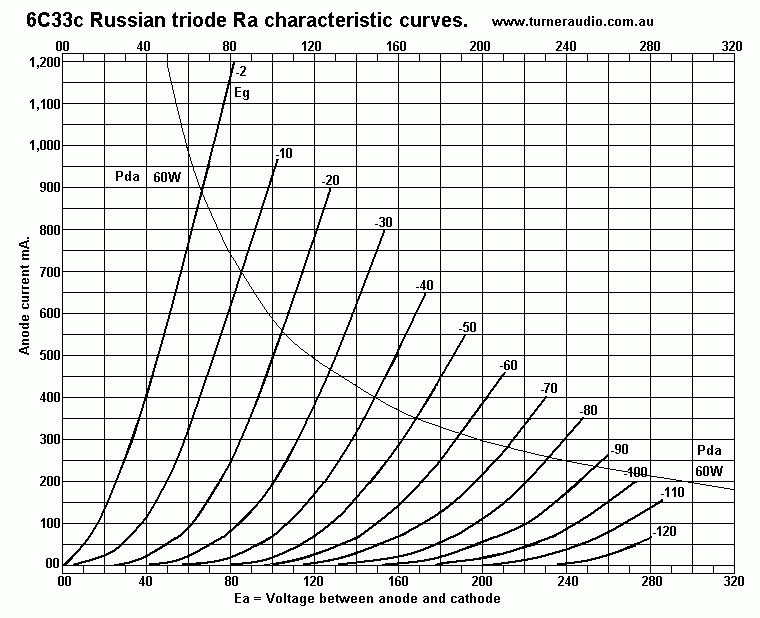
Fig 21. 6C33c Ra curves for anyone to draw their own loadlines.
Definitions of terms used.
OTL amps, strengths and weaknesses.
Some DIYers have occupied an enormous amount of my time with emails about OTL amps,
and I always recommend they use a much higher amp amp load than manufacturers say should be
used. To achieve the higher load for an existing OTL amp one might consider a Speaker Matching
Transformer ( SMT ). output-trans-speaker-matching.html
Most ppl are extremely reluctant to wind any transformer and are completely unskilled.
The easiest option is to just buy a ready made SMT from say http://zeroimpedance.com which
gives them a toroidal SMT with high enough power rating for most OTL amps with say 6 x 6AS7
or 4 x 6C33c.

So just why are tubed OTL amps so technically flawed?

In my humble opinion, all tubed OTL amps are flawed because the tubes used operate in their most
non linear and least efficient manner and are very prone to overheating. And these tubes require at
least 40dB of GNFB to force them to give an acceptable outcome for Rout and damping factor and
THD & IMD. The bandwidth is usually very good because there is no OPT used between tubes
and the speaker load.

The 6AS7 or 6C33c were most commonly used as pass elements in B+ supply rails where there was
no need for the natural linearity given by class A signal operation. RDH4 has a few such schematics
for B+ regulators used mainly in 1955 scientific gear such as oscilloscopes.

However, the 6AS7, 6336, 6080, 6C33c, and others all have properties to allow them to be used
in class A1 and AB1 conditions for audio signal amps In 1955, there was virtually zero demand to
ever use them in audio amps because everyone found it was better to use 6L6, KT66, 6V6, etc.
Then by 1960, we had KT88, 6550, EL34, EL84, and higher AB Po and you could have 30W
class A in 2 channels and with 20dB NFB and you'd get far better sound than any OTL, lower Rout,
lower THD, IMD, and completely adequate bandwidth.

The 6AS7 or 6C33c may be used with output transformers just like any other triode or triode strapped
beam tetrode or pentode. Very few if any amps were commercially manufactured with OPTs for
6AS7 or 6C33c. Thus demand for OPTs and a tradition of use for these low Ra triodes never occurred
because it was always cheaper and easier to buy 6L6, EL34, and cheaper to service and replace such
common tubes.

But all this still leaves all those wondering how to best use 6AS7 & 6C33c in future if a future supply remains.
I have always worried about future supply of uncommonly used tubes like 6AS7, 6C33c, 845, and 13E1.
The fact is that If a "strange amp" can exist, it will be wanted by sumwun@sumwear.
Remarkably, all these uncommon tubes can sound magnificent, but it requires they have operating conditions
very different to what is found in nearly all present day tube OTL amps.

If people do not want to use any OPT with say 6 x 6AS7, then they should consider using say 4 mosfets in
class A-AB and driven by EL34 or EL84 in triode mode. This easily give an excellent OTL amp, and six 
2SK1058 in PP class AB with high idle current will give much better performance than 6 x 6AS7.
I cannot see how 6 x 6AS7 operating in virtual class B conditions with a with a low ohm speaker load and
in with all tubes in the most non linear region of working could ever sound as well as 6 mosfets which
can operate in class A with the same low speaker load, also without without any OPT. This assumes the
mosfets are in quasi series complementary pair mode, but they can be all in source follower mode with
3 x 2SK1058 plus 3 x 2SJ162. I know ppl who have swapped their OTL amps with tube amps with OPTs,
once they realised the OTL was no better, and that the OTL smoked its tubes repeatedly. 

All power triodes, including "low impedance types" such as 6AS7,6080,6336,6C33c, SHOULD HAVE
minimum anode load for class AB never less than twice the Ra as it given in the data sheets. 6AS7 with
both its triodes paralleled has Ra = 140r, so the RLa load should be a minimum of 280r. 6C33c, with Ra at
80r, should not have a load less than 160r. But most speakers are between 3r0 and 9r0, and therefore an
OPT is needed.

With no OPT, and with very low loads < 50r, these low Ra tubes are reduced to work as a non linear
current generator with a load that is a virtual short circuit, with the most non-linear transfer curve at low
levels below 5W which powers most listening levels used at home.
To to get any useful power for the load, there must be at least 2 triodes biased with low Idc for low
idle Pda and these can generate only a tiny amount of class A Po before class B operation continues
to clipping. Using multiple tubes in parallel does little to improve the bastardized tube operation.

The audio signal is grossly distorted when it passes through the very non linear Class B output stage
so a huge amount of GNFB is then required to clean up the mess to get similar measurements as
for conventional transformer loading. It is impossible to fully achieve this.
The output tubes easily overheat and become damaged because peak currents are very high, perhaps
up to an amp or more. Pda heating due to signals = Ea x Ipk x 0.315. if Ea = +150V, peak Idc =
1A, then Pda = 150 x 1 x 0.315 = 47W. 6AS7 has Pda rating of 26W. 6AS7 does not cope well
when Ia max rating of 125mA is grossly exceeded. It arcs over internally.

The low Ra triodes were originally designed to work as series pass elements in series regulators for
B+ supplies to gear with lots of other tubes needing a quiet +350Vdc rail. 6AS7 were common in
tubed oscilloscopes and other scientific gear before 1965.

OTL amps are said to give "very transparent sound" because no OPT is in the signal path. But I see the
transparency is completely ruined from the amount of THD and IMD produced by the virtual class B
operation. The idea that no OPT is good merely warps the minds of irrational audiophiles.

Could tubed OTL amps be made to work better ?

Yes, but not without expense or some mental torture.

1. Rebuild the entire amp to include a specially wound OPT if there is room on the chassis.
Usually an OTL amp with 10 x 6AS7 can have 4 removed, and in their place have an OPT installed
to give far better Hi-Fi performance, more Po, and use far less power from mains, and run cooler.
Such a drastic solution allows the OTL amp to become a normal transformer loaded PP or SE amp,
using the same tubes, usually 6AS7 or 6C33c. The output power will be class AB but have at least
33% of pure class A before the remainder is performed in class B. Such work is well beyond the
capabilities of any audiophile or DIYer. The costs of a custom wound OPT and the drastic alterations
could be high, but then improvements always cost money, and of course the amp resale value may
plummet because the amp is no longer an original example of a brand name model, and buyers of
brand name product are stoic believers in brands, and have low understanding of anything technical.

2. Use an externally connected speaker impedance matching transformer available from
http://www.zeroimpedance.com The Zero Impedance toroidal trannies have at least 20Hz to100kHz BW.
You could have a pair of special speaker matching transformers wound by http://www.tortech.com.au/
I have doubts if Tortech could understand a specification I might write because nearly all their work is
making simple mains transformers. As soon as someone tries to tell them how they want it wound, ie,
the details about wire wire size, the geometry of the windings, insulation, varnishing and multiple taps
then maybe they might not cope very well and the cost would be 3 times a ready made toroidal PT with
one primary and 2 secondaries of the same weight and size.

I cannot advise anyone on exact details of turns and how they might be arranged on a toroidal core,
but here are general ideas :-
The core should be GOSS and have plastic covers each side to ensure wires bend easily around the core
section away from sharp edges. Such core covers should be resistant to high temps of 200C. For an
isolation type with multiple secondary load matches then a primary should wound so half its turns go once
around the toroid, evenly spread. This is covered by woven tape insulation. Each of say 6 sec windings
should be wound right around the circle on top of the first 1/2 primary. A second layer of woven tape is
wound on. A second 1/2 primary is wound over the top of all preceding turns. Woven tape insulation is
used to cover finished windings. The woven tape allows soaking with varnish and baking to give a high
quality.

Want to wind your own toroidal tranny? Try looking at
https://www.youtube.com/watch?v=nyMM3V9bbSQ&nohtml5=False
This video looks like a lot of hard work including making parts on a lathe. Its all too hard for most ppl.
But here there's Yibo toroidal coil winder.....
https://www.youtube.com/watch?v=82PpCzM2CUg
Maybe they are about $3,000 to buy. Getting someone to wind for you is cheaper.

A typical SMT input : output voltage ratio is 2 :1, which gives load ratio 4 :1, ie, the LS Factor for load
increase = X4, so a 4r0 speaker at SMT output then looks like 16r0 at amp output, so 16r0 is the load
for the tubes, instead of 4r0. This vastly improves the way the OTL tubes operate. But the 2:1 voltage ratio
could be much higher for a much greater increase in amp load ohms for much better operation than limiting
load to 16r0. A 3 : 1 turn ratio gives X9 for 36r0 at amp, a 4 : 1 TR gives X16 for 64r0. A 6 : 1 TR gives
X36 for 144r at amp and it becomes possible to operate tubes with far less THD, and with tubes biased for
more idle current and much more class A power. And from a given number of output tubes the maximum
Po can be doubled and there is no risk of smoke.

I have heard nothing but praise about Zero transformers from two locals who used them to make their
low Z speakers look like a higher Z to better suit conventional amplifiers. Many very old amps such as
Quad-II were made for best class A operation with 32r0 or 16r0 with their OPT strapped for 16r0
or 8r0.
Using SMT with X4 Factor, 4 ohms becomes 16r0 or a X8 factor gives 32r0. THEN you the class A
power which sounded so well from these ancient amps.

3. Use an externally connected 500VA+ TOROIDAL mains transformer which was otherwise meant
for a solid state amplifier power supply, and which has P : S ratios of say 120V + 120V mains : 24V+24V.
Hammond Cat No 1182S24 may be OK, it has 117V+117V : 24V+24V.

Basic concerns for low Ra triodes using ISOLATION mains toroidal PTs :-
A. The PT MUST a toroidal type which probably has Secondaries wound over top of Primary to fully
cover the primary, and this becomes equivalent to having multiple interleaving on and E&I core to get good
HF response.

B. DO NOT use an E&I PT for audio. The E&I PT may have all primary wound on first with all Secs wound
on above, with only one interface between P and S = bobbin width. Typical F response will be 3kHz to 5kHz.
Amateur radio operators liked PTs in modulators because their wanted HF response was seldom more than 3kHz.

C. Work out the impedance ratios of the toroid PT in ohms. Example, 500VA, 240V input.
Max input current = 500VA / Vac = 500 / 240Vrms = 2.0833Arms.
Input Primary RL= V / I = 240V / 2.0833 = 115.20 ohms, say 115r.
Suppose 2 Secs are paralleled for = 50V for 500VA. Max Sec output current = 500VA / 50V = 10A.
Output RL = V / I = 50VA / 10 = 5r0. Toroidal PT made in Australia usually have only one 240Vac for 50Hz mains
input winding and UK/Europe have 230Vac. Tables 1-5 cover most of what might be usable.

WARNING. Most OTL amps have a large amount of GNFB, 35dB+ to correct the huge amount of open loop
distortion because tubes are forced to work in their most non linear manner possible, and during the first few
watts of operation used for 95% of listening.

The use of SMT from zeroimpedance.com or a mains PT or any other SMT may possibly make the amp
unstable and oscillate at HF and / or LF if the shunt C or shunt L of the transformer has reactance which
causes enough additional phase shift to make the NFB positive at HF or LF, often below 20Hz or above 30kHz.
However, Such instability is highly unlikely if the amp maker has made sure there are "critical damping networks"
to prevent any oscillation with any possible combination of L, C and R in the load, including not having any load
connected.

Any discussion of GNFB in amplifiers demands some deep understanding of the effect of the amount of
GNFB, the open loop gain F response, the open loop phase shift, and the effects of reducing open loop gain
below 30Hz and above 10kHz using shelving R+C networks, Zobel R+C networks across output, and phase
advance C across GNFB R divider network between output and amp input for GNFB, often the cathode
of an input tube.

Fig 1. Effects of GNFB on typical tube amplifiers.
GNFB-effects-generic-tube-amp-F-response-june-2016.gif
Fig 1 shows curves A, B , C for effects of GNFB on a generic tube amp with an OPT with zero critical
damping or gain shelving. Using only 12dB GNFB will give typical peaked response and with 18dB
the peaks can be +15dB above the reference level for 1kHz. It may be impossible to apply 18dB GNFB
without the amp oscillating at LF and / or HF, and especially when there is no load, or just a 0.22uF C
across output.

Notice that the curve G is the possible result for an OTL amp which has 40dB applied GNFB.
40dB is a huge amount of NFB for any tube amp but quite possible because there is no OPT with at
least 2 added F poles in the open loop gain response, one at LF, the other at HF.

I do not want to repeat here what I have said at my other website pages about basic tube operation
and the principles governing NFB application. I do know many people just cannot understand voltage
gain, phase shift or NFB and many other technical issues.

Tube amps operating mainly in class AB with anode loads = Ea / Ia or higher and with OPTs included
in the NFB do not need more than a total of 20dB NFB including local FB in the output stage and
GNFB. Using more NFB will tend to make the amp unstable, ie, reduce the "margin of stability".

OTL amps operating close to class B need much more GNFB because the tubes operate with loads
which have no relation to Ea / Ia, ie, loads are virtual short circuits, so tubes are current generators
with very non linear transfer function of Vg : Ia. THD / IMD is very without NFB. The amount of
GNFB in many OTL = 40dB, 10 times more than with an OPT. But without an OPT, there is no
bandwidth limiting or phase shift due to OPT so open loop gain may be much wider than with most OPTs.
Therefore it is easier to make the OTL unconditionally stable, but there must be gain shelving R+C
networks and Zobel R+C and C compensation in NFB divider network to ensure stability.
The input and driver stages of an OTL amp may have three C+R coupled tubes which can give a
large amount of LF phase shift and the Miller C of each tube can cause HF phase shift which can
provoke oscillations at F higher than for a normal amp with OPT.

Unless the laws laid down by Bode and Nyquist are respected, all amplifiers with NFB will oscillate.

So what is the effect on stability and voltage gain of using an external SMT for OTL? Assume there
are 8 x 6AS7 in Series Pair, for 8r0 load without any SMT, and 64r with an SMT with impedance
factor 8:1, ie with TR = 2.83:1.
Consider one 6AS7 in the above 8 tubes in OTL, see Fig 2 below.
No SMT, RL = 32r. You need Vg pk = +60V to get Ea swing = -33Vpk. Overall voltage gain
= 33V / 60V = 0.55. But for Va = -6.4Vpk, you need Vg +20Vpk, so initial gain = 6.4V / 20V = 0.32.
With SMT, RL = 256r. You need Vg pk = +60V to get Ea swing = -85Vpk.
Overall voltage gain = 85V / 60V = 1.41. For Va swing -25Vpk, you need Vg +20Vpk, so initial gain
= 25V / 20V = 1.25.

The difference of initial gain for the change of load from 32r to 256r = 1.25 / 0.32 = 3.9x.
If the OTL amp has 40dB GNFB with 8r0 load, then it is increased to 52dB with load of 64r.
The THD / IMD is reduced by about -10dB due to change of load, and by another -12dB by increase
in NFB, ie, -22dB total, so the effect of SMT reduces THD / IMD about 10 times, so instead of say
0.5% at clipping, you should get 0.05%, not a bad result at all. The damping factor is also increased by
10 times.

Without any load connected to an OTL amp, voltage gain of 6AS7 will be highest it can ever be, and
equal to amplification factor µ for the tube at the idle Iadc = 1.9. So without any load, the amount of NFB
is about 56dB, or 16dB above the NFB used where load = 8r0. Manufacturers would need to ensure the
amp is stable without a load and with such a high amount of NFB, with similar measures to those used in
solid state amps.
------------------------------------------------------------------------------------------------------
Here are some possible uses of mains toroidal transformers for audio F :-
Table1. Jaycar 500VA toroidal mains PT, cat no MT-2146.
Mains PT.
500VA.
Pri Vin
50Hz.  
Secondary
Vrms with
Mains
primary
input, 1.25 Tesla.
P:S Turn Ratio P:S Z Ratio Prim
max
Vrms  20Hz,  1.25
Tesla.
Prim
Z load,  r.

Sec Vrms
max
Sec
Z load, r.
Power output, W Winding
losses,
total %
240V
50V//50V
4.8 :1 23 :1
96V
115r
20V
5r0
80W
7%
240V
50V//50V
4.8 :1
23 :1
96V
58r
20V
2r5
160W
14%
240V
50V+50V
2.4 :1
5.8 :1
96V
58r
40V
10r0
160W
14%
The single mains winding allows feed from only single output from OTL.

Table 2. Auto-transformer use for Jaycar PT, cat no MT-2146.
Mains PT.
500VA.
603VA
auto-T Vin
50Hz.  
Secondary
Vrms with 
Mains
primary
input, 1.25 Tesla.
P:S Turn Ratio P:S Z Ratio Prim
max
Vrms  20Hz,  1.25
Tesla.
Prim
Z load,  r.

Sec Vrms
max
Sec
Z load, r.
Power output, W Winding
losses,
total %
240V
+50V
50V//50V
5.8 :1 33.6:1
116V
140r
20V
4r2
95W
6%
240V
+50V
50V//50V
5.8 :1
33.6:1
116V
280r
20V
8r4
47W
3%
240V
+100V
50V+50V
3.4 :1
11.6:1
136V
164r
48V
11r7
196W
6%
240V
+100V
50V+50V
3.4:1
11.6:1
136V
82r
48V
5r9
390W
12%
The auto-transformer with one mains winding allows feed from only single output from OTL.

There is a possible 625VA toroidal listed at www.rsaustralia.com
See Cat No 223-8336.
It is for 230V ( one winding ) to 45V + 45V, for X6.53 and X26.1
Data is at
http://docs-asia.electrocomponents.com/webdocs/0027/0900766b80027b4c.pdf
Series Secs, ZR = 85r : 13r0. Parallel Secs ZR = 85 : 3r3 and Rw losses = 5.8%.
170r : to 26r0 or 6r6 with 2.9% losses.

The has very similar TR to the Jaycar MT-2146 but higher VA
for both isolation or auto mode, giving lower primary RL and lower sec loads.

Despite fairly high weight & size, they could be used with series connected
tubes which operate from +/- 125Vdc rails.

One might assume the primary turns for RS 223-8336 are wound on first to go around the core
in an even number of whole core circles. One might hope each secondary winding also goes
around the circle at least once, and if the toroid hole = 60mm dia, circumference = 185mm,
and if wire oa dia = 2.2mm, there is room for 84t without any crossed over turns.
Working backwards from known Vac, and Ns for 45V, Afe will have to be 2,017 sq.mm for Bac
1.2Tesla at 50Hz, and that means core strip build up could be 40mm, and height of core, or strip
width = 60mm.

There are two more possibilities from USA where mains = 117Vac.
Table 2. Hammond Engineering 500VA, Isolation type 1182S24.
Mains PT.
500VA.
Pri Vin
60Hz.  
Secondary
Vrms with 
Mains Vin,
1.25 Tesla.
P:S Turn Ratio P:S Z Ratio Prim
max
Vrms  20Hz,  1.25T
Prim
Z load,  r.

Sec Vrms
max
Sec
Z load, r.
Power output, W Winding
losses,
total %
2//117V
15V//15V
7.8 :1 60.8:1
39V
27r4
5.0V
0r45
55W
7%
2//117V
15V+15V
3.9 :1
15.2:1
39V
27r4
10V
1r8
55W
7%
2//117V
15V+15V
3.9 :1
15.2:1
39V
54r8
10V
3r6
27r5
3.5%

Table 3. Auto transformer use for Ham.Eng Isol type 1182S24.
Mains PT.
500VA.
653VA for auto T.
Pri Vin
60Hz.  
Secondary
Vrms with 
Mains Vin,
1.25 Tesla.
P:S Turn Ratio P:S Z Ratio Prim
max
Vrms  20Hz,  1.25T
Prim
Z load,  r.

Sec Vrms
max
Sec
Z load, r.
Power output, W Winding
losses,
total %
2x117V+15V
264V +CT
+15V-15V
CT only.
8.8:1 77.4:1
+44V
-44V
124r
+5.0V
-5.0V
1r6
62W
6%
2x117V+15V
264V +CT
+15V-15V
CT only.
8.8:1
77.4:1
+44V
-44V
248r
+5.0V
-5.0V
3r2
31W
3%
2x117V+15V
264V +CT
+15V-15V
CT only.
8.8:1
77.4:1
+44V
-44V
496r
+5.0V
-5.0V
6r4
15.5
1.5%

Table 4. Hammond Engineering 625VA, Isolation type 1182T24
Mains PT.
625VA.
Pri Vin
60Hz.  
Secondary
Vrms with 
Mains Vin,
1.25 Tesla.
P:S Turn Ratio P:S Z Ratio Prim
max
Vrms  20Hz,  1.25T
Prim
Z load,  r.

Sec Vrms
max
Sec
Z load, r.
Power output, W Winding
losses,
total %
2//117V
24V//24V
4.87:1 23.8:1
39V
22r
8.0V
0r93
68W
6%
2//117V
24V+24V
2.44:1
5.93:1
39V
22r
16V
3r7
68W
6%
2//117V
24V+24V
2.33:1
23.7:1
39V
44r 16V
7r4
34W
3.5%
117V+117V 24V+24V
4.87:1
23.8:1
78V
88r
16V
3r7
68W
6%

Table 5. Auto-transformer use for Ham.Eng Isol type no 1182T24.
Mains PT.
625VA.
752VA for Auto-T
Pri Vin, at
60Hz.  
Secondary
Vrms with 
Mains Vin,
1.25 Tesla.
P:S Turn Ratio P:S
Z Ratio
Prim
max
Vrms  20Hz,  1.25T
Prim
Z load,  r.

Sec Vrms
max
Sec
Z load, r.
Power output, W Winding
losses,
total %
2x117V+24V
282V +CT
24V+24V
only.
5.88:1 34.5:1
+47V
-47V
106r
16V +CT
3r07
68W
5%?
2x117V+24V
282V +CT
24V+24V
only.
5.88:1 34.5:1 +47V
-47V
212r
16V
+CT
6r2
34W
2.5%?
Tables 1 to 5 could confuse many ppl, but my pages might appeal to those who consider many
possibilities, and choose from what is affordable and available, then spend days working out
amps on paper or in a simulation program.

Table 5 gives an interesting input load for normal PP operation for cathode follower use of 6AS7 or
6C33c. The auto-transformer connection is possible, and there should be low leakage inductance
and good HF between "primaries and secondaries". These both exist in ONE winding, with Primary
being all turns between the Vac input and 0V, and the Secondary being the lesser turns in the COMMON
part of primary, or shared portion of all primary turns. The use of a CT to 0V puts all turns at close
to 0V potential. The Idc of tubes on each side of PP circuit will make a little Vdc across each
1/2 primary but at each end of secondaries with CT, the Vdc is low, and balanced, so has no bad
effect on a speaker.

With Output RL = 4r6, use of any speaker above 2r0 should be OK. But with 4r6, RL at input = 159r,
and let us add 4% for Rw, say 166r. The class A load for tubes each side of PP circuit is 83r.
In class AB, when tubes on one side have cut off, the load reduces to 41r. This all looks promisingly good.

Note. Input VA rating can be higher for auto-transformer use of an isolation transformer.
Consider Hammond 1182T24. It is rated for 625VA with 117V or 234Vrms input at 60Hz.
Max current in each 117V primary = 2.67Arms. With auto-transformer connection, max current
in 117V part of primary can be 2.67A, but the added 24V of series secondaries mean there is 141Vrms
at each side of CT for total allowed Vac input = 282Vrms, so VA = 282V x 2.67A = 752VA.
The input RL = 282V / 2.67A = 106r. To get this input RL, the sec RL = 3r07.

Note. Mains toroidal PTs may have Np and Afe suitable for Bac up to 1.5Tesla at 50Hz or 60Hz, for the
mains Vac. I have based my calcs on 1.2Tesla, and it cannot be known what Bac max has been used.
For 1.2Tesla at 20Hz, 60Hz transformers must have mains Vac divided by 3, so 117Vac is reduced to only
39Vac. If the transformer was designed to run at Bac 1.5T, then you get 1.5T at 20Hz, 39Vac. For UK,
Europe, Aust, Asia, the 50Hz mains Vac must be divided by 2.5 for 1.2T at 20Hz, so for Aust, max Vin
= 240 / 2.5 = 96Vac.

If the maximum Vac max is always to be say 1/3 of the mains Vac, then the input power is 1/9 of VA rating
for the same RL input loads as for mains. So a 625VA PT could only have 69W applied at its input at
20Hz and to the same loads for mains use, and with same winding loss%, say 5%. The loads could indeed
be reduced to allow higher current and more input power but if the input and output load ohms are halved,
the winding losses double.

Therefore the VA rating for a toroidal PT should be about 10 times the outputpower of the OTL amp when
loaded by 8r0 without any transformer connected.

So an OTL amp which makes 40W with 8r0 may need an mains PT meant for 400W at least. A 40VA
mains tranny just will not work. Winding losses will be way too high, 50% +.
--------------------------------------------------------------------------------------------------
Let us explore use of ONE PAIR of 6AS7 to drive typical speaker loads.
Fig 2. Low RL loadlines for 6AS7.
6AS7G-OTL-4r-64r-AB1-loadlines-19-dec-2013.gif
Fig 2 shows FIVE loadlines between 4r0 and 64r, for one 6AS7 used in a pair for nearly class B PP
operation, low idle bias Idc = 50mAdc, Ea = +120Vdc, grid bias = -53Vdc. Each 6AS7 have the
same load as in Fig 1A, and each works the same way to take turns to increase positive or negative
going currents. The current wave form in each tube is like that in a resistance fed by voltage source
with a tube diode in series, ie, like the waves in a tube rectifier in a PSU, but without a reservoir cap.
 
The straight lines drawn from the Ea idle point at Q are for loads of 4r0 to 64r. They stop at the curve
for Eg = 0V, because the grid input resistance changes from above 100k to a low resistance of 1k0
when grid voltage becomes positive above cathode, thus attracting electrons. This low resistance
limits the output of most driver tubes unless they are arranged as cathode followers capable of AB2
operation. The Ra curve for Eg1 = 0V is a boundary which limits Ea swing. But direct coupled cathode
follower drive to 6AS7 grids is a sure way to cause overheating in all output tubes. Don't even consider it.

The idle Ea has large effect on thermal stability and possible overheating. Lower Ea gives less Po with
less Ia swing because of Ea = 0V curve. But there is lower maximum heat Pda. More tubes are needed
for the same Po. Higher Ea gives higher Po and higher maximum Pda, and with increased risk of
thermal run-away.

Data sheets for 6AS7,6336, 6080 will show maximum peak Ia on curves could be many times what
may be tolerated in the tube with music. Tube curves may have been plotted using low duration pulse
type signals, and hence the tube survived the stresses imposed by tube curve plotting circuits. Data sheet
text says max Ia rating for each triode within 6AS7 = 125mA, so Ia max for both triodes of a whole 6AS7
= 250mA.
If you try to force 6AS7 to conduct say 1.4A peak for a 1/2 sine wave, the tube will arc over internally
from anode to cathode and fail sooner rather than later. I have seen this occur in a pair of 6AS7 I once
used in a bench top PSU for B+ regulator, and while I examined the behaviour of a prototype Series Pair
of 6AS7 in amp to explore their abilities. I later completely re-built the bench top PSU using all solid
state devices.

IMHO, Ia peak swing in a 6AS7 should never exceed 0.5Apk. 6C33c is also known to be capable of
3A peak, but this should never be the basis of any amp design.

Fig 3. Anode power dissipation, Pda.
6AS7G-OTL-aB1-Po-vs-Pda-vs-RL-21-april-2016.GIF 
Fig 3 shows curve for max Po versus RL for 2 x 6AS7 in a Series Pair OTL amp.
When only 4W of audio is being produced in 4r0, the Pda for each 6AS7 = 52W !!!

For continuous sine wave operation Pda reduces as the load increases and so does the Po and the
efficiency. The tubes are most efficient with load = 48r, where Po = 18.4W and Pda = 24W in
each 6AS7, close to the Pda rating limit. Max class B1 Po = 18.5W with 56r. and Pda = 22W.

The graph shows that if the speaker Z = 4r0, you would need 12 pairs of 6AS7 to ensure each
pair is loaded by 48r. You would get Po = 12 x 18.4W = 220W. A continuous sine wave at
clipping produces Psa total = 24 x 24W = 576W of anode heat. Anode AB efficiency = 38%,
and you need 378W of filament power to the 24 x 6AS7. Such an amp might be a useful room
heater if you live in Siberia, and you can afford the bills from the Siberian Electricity Company.

In 1955, most speakers were 16r0, with much higher sensitivity than 2016. Therefore you needed
only 3 pairs of 6AS7 to give a load of 48r of each pair, Po max = 3 x 18.4W = 55.2W, which is
100 times more than the 0.55W one might use as average Po to one 16r0 speaker. Maximum
anode heat = 3 x 24W = 72W. Filament heating = 94.5W, and this is much more affordable.

Calculations for 16r0 for 2 x 6AS7 show Pda max occurs at lower than clipping levels, and
as shown on Fig 3 :-
Po = 4.1W, Pda = 25W.
Po = 8.2W, Pda = 34.5W.
Max Po =12.5W, Pda = 40W.

All class B amps will produce alarmingly high Pda at low power levels. For each RL listed, there will be a
different Pda Vs Po curve and its all bad news for anyone wanting too crank up the volume with a 4r0 speaker
and without enough 6AS7 present. Fig 4 table below shows the problem with only 2 x 6AS7.

With just 2 pairs of 6AS7, a speaker matching transformer with TR 3 : 1 has ZR 9 : 1 which transforms 4r0
to become 36r so that RL for each pair = 72r. Fig 3 graph above shows 1 pair 6AS7 giving Po = 18W max and
Pda max per tube also = 18W, and for 2 pairs you get Po max 36W. This is a HUGELY BETTER outcome than
without the SMT.
---------------------------------------------------------------------------------------------------
In Fig 2 above, the loadlines for 4r0 up to 256r are up to the point of clipping where each load line intersects the Ra
curve for Eg1 = 0V. The audio output power and Pda may easily be calculated from Ia and Ea figures in the graphs.
Without explaining just how the equation below was derived, the total heat, Pda, generated in tubes due to signal
operation can be calculated for a Series Pair of tubes :-

Pda = Va x ( [ 0.45 x Ea ] - Vo ) / RL, Pda in Watts for all tubes, Va = Va-k in Vrms, 0.45 is a constant, Ea = Vdc
between anode and cathode, and RL is in ohms.

The same formula applies to Series Pair class B mosfets or BJTs. The Va = Vrms at load, ie between Vo output and
0V, and Ea is the sum of Vdc across both devices, ie, with +/- 30Vdc rails, Ea = 60V.

A pair of 6AS7 with a 4r0 load with Ea = +120V can only manage a theoretical 1.4A pk which could cause arcing.
If the peak current is limited to 0.5Apk, load has to be 128r, see load line in Fig 2 above. But if RL = 4r0, Vo = 4Vrms.
Total Pda = 4Vrms x ( [ 0.45 x 240Vdc ] - 4Vrms ) / 4r0 = 103W. The heat in each 6AS7 = 51.5W and twice the Pda
safe rating. Anode efficiency = 3.7%, a truly horrid result! At Po = 1W, the 4r0 load has raised Pda for each 6AS7 to
26.5W.

If load = 64r, then Ia pk = 0.77A so V RL = +/-49.28Vpk = 34.84Vrms so Po = 19W.
Total Pda = 34.8 x ( [ 0.45 x 240Vdc ] - 34.8 ) / 64r = 39.8W. Each tube has to manage Pda =19.9W, less than the
25W rating. Efficiency = 32.3%, and better than using any lower value RL. But the threat of arcing remains.

The other formula for working out Pda in any tube in any amp :-
Pda = ( Average Ia x Ea ) - Po in Watts.
Or also, Pda =  DC power from PSU - Po, which is the easiest to measure if there is a convenient 10r0 current sensing
R before the B+ output from a filter cap.
Pda = ( Ea x Iadc ) - ( Vac RL squared / RL ) Watts.
This is a very simple calculation for idle condition with constant Ea and Iadc. But calculations frighten 97% of the population.
This is why so many bad quality products have been sold to the public since Time began. Few ppl understand basic energy
flows and heat losses within amplifier devices.

Fig 4. Graph for Pda versus Po for 5 loads between 4r0 and 64r.
Graph-Pda-vs-RL-OTL-2x6AS7.GIF
Fig 4 graphs show the Pda Vs Po level for ONE PAIR of 6AS7 in OTL with five RL between 4r0 and 64r,
and in virtual class B1 operation with low idle bias Iadc. The Vac is a sine wave. Each 6AS7 idles with Ea 120V,
Iadc = 50mA, idle Pda = 6W, and with filament heat of 16W, idle Pd total = 22W total. Data sheet says Pda max
= 13W for each triode, so 26W for both, so the total Pda + heaters = 26W + 16W = 42W, and the tube
temperature climbs to the rated data temperature limit at least, but may rise much higher if a single tube is
surrounded by other tubes in on a hot summer day! So the Pda ratings are optimistic, and continuous sine wave
operation which produces Pda = Pda limit MUST be avoided at all costs!!!

The graphs are only concerned with Pda, not heater Pd.

With a 4r0 load, the Pda rises from 12W at idle to 52W at only 1W of Po. Music has much varying levels between
soft and loud. So the average level of music could be at 1W, with peaks rising to clipping levels at 4W, and the tubes
are already very hot. Many ppl will want music to be louder, and 2 x 6AS7 in an OTL will soon melt down to
destruction with 4r0 loads. The load should be 48r if you want to drive the amp hard with a tuneless noisy ditty from
a Heavy Metal band.

Using Ea = +135Vdc or +150Vdc makes everything a lot worse.

Some OTL have 10 x 6AS7 per channel, and barely enough. 6 could be removed, and an OPT installed, and
the remaining 4 would produce far better quality class AB Po and better sound than the original 10. Some amp
makers just sell you lots of tubes instead of the much more expensive OPT, and yet the amp price remains high.
IMHO, it is a bargain with a Devil.

I should dare to mention solid state. The peak currents of the low µ triodes used for OTL cannot ever be as high
as those generated in power mosfets or transistors. For 2SK1058, max Ipk = 7 Amps, and Pdd rating is listed
at 100W. Max temp is listed at 150C. Only a complete idiot would ever set up a 2SK1058 so that could ever
get near 150C, and the Pda rating is for a short time pulse.
For continuous sine waves in a class B amp the Pda for a single 2SK1058 of  TO3P package type should never
endure a constant average Pda above 25W.
With +/- Vdc rails of +/-30Vdc and two generic series pair TO3P mosfets, the Vd pk swing = +/-25Vpk, so
17.68Vrms is available for 4r0 load, Po = 78.1W.

Pdd = Vo x ( [ 0.45 x B+ ] - Vo ) / RL = 17.7V x ( [ 0.45 x 60V ] - 17.7V ) / 4r0 = 41.15W, ie, 20.6W
in each mosfet.

Class B amps have maximum Pdd at 2/3 max Po, in this case at 52W, and 14.42Vrms into 4r0;
Pdd = 45.35W total so 22.67W max for each mosfet.

To get 50W to 4r0 with 6AS7 OTL and with no SMT, I calculate 14 x 6AS7 in 7 parallel pairs are needed,
each pair makes 7.1W with RL = 28r, and Pda per tube will be about 25W. For more about mosfets in
output stages with tubes for input and drivers, see my page on solid state with tubed input.
-------------------------------------------------------------------------------------------------
What about Class A or AB operation?
Fig 5. Class A for 6AS7.
6AS7G-pure-classA1-loadlines-19-dec-10-2013.GIF
Fig 5 shows the 832r load line for pure class A1 for one 6AS7 with both its triodes paralleled for an SET
amp or for one tube of a PP pair of 6AS7. Each tube has Ea = +150Vdc, Iadc = 133mA, Pda = 20W,
and Eg1 fixed bias at -65Vdc.
Class A RLa for max Po may be calculated, RLa = ( Ea / Ia ) - (2 x Ra ) where Ra is calculated from Ra
curve for Eg1 = 0V between 0.0mA and 2 x Iadc, seen here as pt A to 0.0.
This case, RL = ( 150V / 133mA ) - ( 2 x 130r ) = 1,125r - 260r = 865r approx.

To determine the RLa graphically for pure class A1 :-
Plot point Q. Let Ea = +150V, let Pda = 20W, then Ia dc = 20W / 150V = 133mA.
Plot point A on Ra curve for Eg = 0V where Ia = twice idle Ia = 266mA.
Draw straight line from Q to A, then project line to B and C.
The line BAQC has V range 0V to C = +262V, and I range from 0mA to B = 302mA.
Therefore BAQC has resistance = 258V / 310mA = 832r = load value
for maximum possible pure class A for one 6AS7 tube with both triodes in parallel.
Max possible SET class A1 Po = 0.5 x Iadc squared x RL, RL in ohms as calculated or found graphically.
In this case, Class A1 Po = 0.5 x 0.133A x 0.133A x 832r = 7.36W. In practice, this Po can only occur
if there is a lot of NFB to force the Ea swing each side of idle to be about equal, ie, THD < 1%.
Without NFB the THD = 12%, mainly 2H. Expect 6.6W at clipping without any NFB. Efficiency is up to 36%
with NFB. 

Where TWO tubes are working in PP, the 2H of each tube cancels, but the 3H of each tube does not, and
is created by the asymmetrical wave shape of 2H of current in each tube. Class B generates 3H where 3H
wave peaks add to 1H wave peaks, giving a pointy peaks on a sine wave, and s-bend at 0V crossings.
Over loaded class A amps create 3H wave peaks which subtract from peaks of 1H, so the sine waves
begin to have flattened peaks, but zero crossings remain free of S bend.

Without GNFB the class A Po for 2 x 6AS7 will be at least twice the class A1 Po for one 6AS7, ie,
2 x 6.6W = 13.2W, Expect 2% of 3H. 12dB GNFB reduces this to 0.5%, and Po is increased slightly to
about 14.7W. The THD reduces linearly with Vo and at 1W for average listening the THD may be 0.12%,
and tolerable. 20dB GNFB will reduce max THD from 2% to 0.2% at clipping, and at 1W THD = 0.05%,
and the IMD and other noise will be extremely low, and the sound will be excellent. The outcome in not as
 good as use of a pair of KT66 or EL34 in triode and loaded optimally where without GNFB the THD is
1% at about 13W. 20dB reduces this to 0.1%, and at 1W the THD = 0.03%.

If the circuit is a "normal PP amp" with CT OPT and B+ feed to CT and with both cathodes grounded,
the OPT has a primary RLa-a = twice the class A1 load for 1 tube, ie, 2 x 832r = 1,664r. Secondary
loads can be 4r, 8r, 16r. Hammond Engineering do not make anything suitable.

The Pda in all pure Class A1 amps is always highest at idle and without any signal. The PSU delivers
constant B+ and Iadc to tubes between zero signal and clipping in all class A1 amps. As the audio Po
increases the Pda reduces to a minimum Pda = Pda at idle - Po. The class A tubes cool down !! 

Using 4 x 6AS7, the PP OPT with CT can have primary PLa-a of 832r with CT, and same 4r, 8r, 16r sec
loads, and PO max = 26.5W at least, all pure class A. Where each has Pda = 20W, the total Pda would be
80W, and maximum Po = 26.5W. While this much Po is made, the Pda = 80W - 26.5W = 53.5W, and each
tube has Pda = 13.37W, OPT with CT for normal PP class A1 will have Z ratio 832r : 4r,8r,16r, or just have
832r : 5r0 which allows all loads above 3r0.

Series Pair or Circlotron with 4 x 6AS7, the OPT would have ZR 208r : 4r, 8r, 16r, or just 208r : 5r0.

In practice, Pda hardly changes in class A because average audio power is low, and not enough to cause any
"tube cooling". But the tubes won't  overheat, unless they have bias problems, or a teenager works the volume
pot, or an idiot connects a very low Z speaker with very low sensitivity to amp outlet labelled 16r0.

Each tube MUST have its own grid voltage bias supply, or have its own R+C bias network. With 6AS7 with
Eg-k = -65Vdc, and idle Ia = 133mA, the cathode bias Rk = 488r, and its heat = 8.6W, and for 4 x 6AS7,
there is 34.4W generated under the chassis, so all things get hot. The best place for such hot R is on a heatsink
above the chassis and away from tubes or electrolytic caps.

Sooner or later an idiot will try to use a 4r0 speaker at 16r0 outlet at high levels. The the tubes may overheat
badly. A shorted speaker cable can cause tube failure. An active protection circuit is needed to outsmart all
idiots.

The 4 x 6AS7 working in pure PP class A1 will sound far better than any OTL amp.

If 2 x 6AS7 or 4 x 6AS7 are in parallel SET mode, the primary OPT load = 416r or 208r respectively.
There will be far more THD and IMD than a PP amp, but most ppl will find the sound to be OK if enough
GNFB is used and an SE triode driver stage is arranged to allow some 2H cancellation. While good, the
SE amp 4 x 6AS7 just will not be as good as 4 x EL34 in parallel pentode mode with an OPT with a 20%
CFB winding. Such windings are of little benefit with 6AS7 ( or 6C33c ) because the tube gain is so low,
the CFB makes little difference because THD and gain is reduced by factor = A / ( 1 + [ A x ß ] ), and
open loop gain is about 1.5 and even with cathode follower connection where ß = 1.0, THD correction
factor = 1.5 / 2.5 = 0.6, only -5dB, and the max Vac needed to drive each grid > 110Vrms.

A quad of 6AS7 in PP class A1 or AB1 can be arranged in Series Pair as for most OTL amps, then
an OPT may be "externally connected" where otherwise there might be a low Z speaker. For SP pure
class A1, each tube has Ea = +150V, Ia = 133mAdc, and can be operated with rails at +150V and -150V,
or from a single B+ rail at +300Vdc. The load of each tube is 832r, and output load is 208r for 4 tubes,
same as for 2 parallel SE tubes. But the PP operation has each tube delivering power to ONE load with
opposite phases so 2H cancellation occurs, just the same as for the 4 tubes in a conventional class A PP
amp with OPT with CT, and where the load across whole primary = 832r.
The OPT for Series Pair tubes does not need a CT on its primary, and needs no air gap in the core because
no Idc flows through the primary winding as occurs in all SET amps. But the Idc must be kept out of OPT
primary if one end of primary is taken to 0V with the other end connected to the anode-cathode join via a
suitable sized C. For OPT primary of 208r, use 2 parallel 470uF rated for 450V, and the -3dB pole is at
0.81Hz.  Bypass the electros with 10uF polypropylene motor start caps rated for 400V.

For primary Pin = 26.5W, Vin = 74Vrms.
For secondary Po = 26.5W into RL 5r0, V RL = 11.5Vrms.
OPT ZR = 208 : 5 = 41.6 : 1, TR = 6.45 : 1.

For class AB1, Ea may be +150V for every tube. Idle Iadc need not be as high for class A, 75mA will
be fine, for Pda = 11.2W per 6AS7. Power into class A loads mentioned becomes class AB, but with
enough initial pure class A for low THD. You will find the PP AB1 load could be 1/2 the pure class A
load, so for 4 tubes with series connection and 208r nominal load could handle 104r. The series
connection produces identical AB1 Po as for conventional PP with OPT with CT.
Peak Va, each tube = 100V = 70.7Vrms = primary Vin to 104r, so AB Po = 48W.

For various numbers of 6AS7, read Table 2 below for OPT ratios needed. I have included for 6C33c,
because 2 x 6AS7 are about equivalent to ONE 6C33c in general capability.

Table 6. Pure class A1 operation.
Pairs of
SERIES tubes.
OPT
prim load
TR for
4r0 sec
TR for
8r0 sec
TR for
16r0 sec
Po
class A1

1 pair 6AS7.
416r
10 : 1
7 : 1
5 :1 13W
2 pairs 6AS7,
or 1 pair 6C33c.
208r
7 : 1
5 : 1
3.5 : 1
26W
3 pairs 6AS7.
139r
6 :1 
4 : 1
3 :1
39W
4 pairs 6AS7,
or 2 pairs 6C33c.
104r
5 : 1
3.5 : 1
2.5 : 1
52W
For where the idle current is lower than required for only pure Class A1 operation, the PP amp will
usually be able to make slightly more Po than for pure class A1 if the load is same as for max class A1.
But with lower Iadc, max Po becomes class AB1 power because tubes on each side of the PP circuit
cut off during part of each wave cycle. The current change in each tube is from idle 75mA to 0.0mA
and from idle 75mA to more than twice the idle current.

The minimum class AB1 load for 2 tubes may be less than the class A load and with idle current less
than for maximum class A, and the operation with music can still provide low overall THD and IMD
and low Pda.

Fig 6. Class AB for 6AS7.
6AS7G-classAB-loadlines-OPT-19-dec-10-2013.GIF
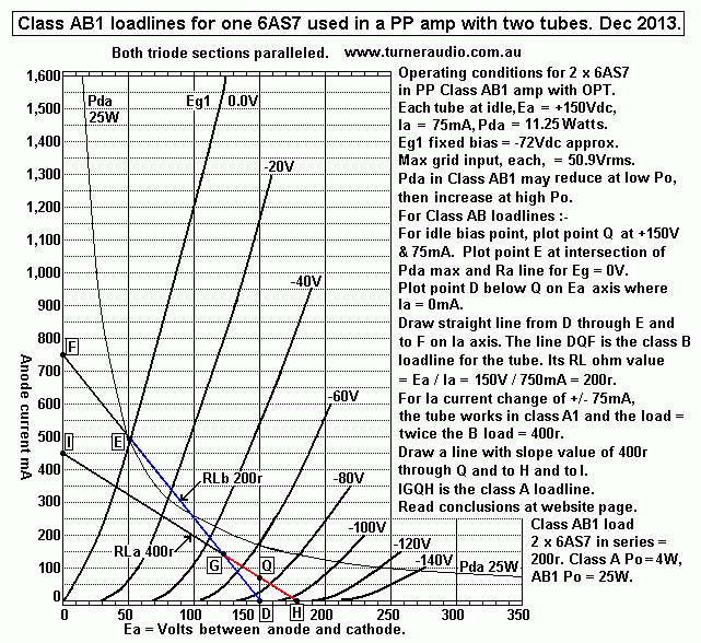
Fig 6 shows 400r class A loadline G-Q-H and class B loadline 200r E-G for class AB1 operation with
RLa just under 1/2 that for maximum pure class A. Idle Ia is reduced from 133mAdc to 75mAdc, but it
is enough to reduce crossover distortion to low levels. The class A1 loadline G-Q-H is quite short, with
Va swings of only +/-30Vpk.
Each 6AS7 makes only 1.1W in class A, two 6AS7 make 2.2W. Beyond 2.2W, all Po is class AB and
each tube works with RLa line G-E = 200r. Each 6AS7 can make 0.5A pk for Va-a = 196Vpk,
138.6Vrms, for max total AB Po = 24W.

This is well above the maximum class A of 9.8W for the same Ea & Ia conditions with RLa-a = 3k5, with
class A load on each tube = 1k75. Purists will sneer at class AB, and insist 4 x 6AS7 be used to make a
total of 19.6W of pure class A with RLa-a = 1k8.

With Series Pair PP, primary load = 200r, and Vpk load swing = 98Vpk = 69.3Vrms which also gives
24W class AB.

More than one pair of 6AS7 results in better fidelity because the power ceiling is higher, while most people
won't want any increase in SPL.

Table 7. Class AB1 operation with normal PP OPT with CT for B+.
Pairs of
normal PP tubes.
OPT RLa-a
pri load
TR for
4r0 sec
TR for
8r0 sec
TR for
16r0 sec.
Class AB
Po
1 pair 6AS7.
800r
14 : 1
10 : 1
7 : 1
25W
2 pairs 6AS7,
1 pair 6C33c.
400r
10 : 1
7 : 1
5 : 1
50W
3 pairs 6AS7,
266r
8 : 1
5.6 : 1
4 : 1
75W
4 pairs 6AS7,
2 pairs 6C33c.
200r
7 : 1
5 : 1
3.5 : 1
100W

Table 8. Class AB1 operation with Series Pair tubes and "external" OPT or SMT.
Pairs of
Series tubes.
OPT pri
load
TR for
4r0 sec
TR for
8r0 sec
TR for
16r0 sec
Class AB
Po
1 pair 6AS7. 200r
7 : 1
5 : 1
3.5 : 1
25W
2 pairs 6AS7,
1 pair 6C33c.
100r
5 : 1
3.5 : 1
2.5 : 1
50W
3 pairs 6AS7, 66r
4 : 1
2.8 : 1
2 : 1
75W
4 pairs 6AS7,
2 pairs 6C33c.
50r
3.5 : 1
2.5 : 1
1.8 : 1
100W

The Turn Ratios used for the external OPT for series connected tubes are all quite low.

Consider use of 4 x 6AS7 or 2 x 6C33c and in Series Pair connection. Minimum load is 100r, and
there is 50W, and VRL = 70.7Vrms. The transformer should be rated for 71Vrms max input and give
Bac < 1.2Tesla at 20Hz.
After some Googling again, I found :-
http://www.parts-express.com/avel-y236853-625va-40v-40v-toroidal-transformer--122-690
Data is at
http://www.parts-express.com/pedocs/specs/avel-toroidal-transformer-specifications-45735.pdf

This is a 625VA toroidal PT for $98.0. It has 2 x 115V primaries with 2 x 40V secondaries in parallel
for load ratio of 86r : 2r56, ZR = 33.6 : 1. Copper losses are 4.3% For 100r minimum load for the tubes,
secondary speaker load = 3r0, so I guess all speakers above 3r0 will be happily powered. The amp
load is higher than rated load for PT use so copper losses = 3.6%. Weight = 4.9Kg.
If mains Vin = 230V, then assume Bac = 1.2Tesla at 50Hz. With Vin = 71Vrms, then Bac = 1.2Tesla
at 15.4Hz, and quite acceptable.

The weight and Cu losses for this toroidal PT are both about the same for a well designed 50W OPT
using E&I core.

The toroidal speaker matching transformers by www.zeroimpedance.com may possibly be OK but I
cannot be sure, because the exact details of winding resistance, max Vin for Bac 1.2T at 20Hz are
nowhere to be found, not even at http://www.zeroimpedance.com/zeroimpedance_007.htm where
Paul Speltz talks a lot on how and why he produced his toroidal SMTs. He does say how he did try
300VA toroidal PTs and got good sounding results. But no details are given for exact working Vac and
current ratings.

In Australia, 300VA toroidal PTs are sold at www.altronics.com.au See cat nos M5518 to M5545
which have 240V : 2 x 18V, 25V, 30V, 35V, 45V.
Also at www.jaycar.com.au,
300VA MT-2130 to MT2144, with 240V : 2 x 12V, 18V, 40V, 50V.
500VA MT-2146, 240V : 2 x 50V.

MT-2144 300VA has Primary RL = 192r. With parallel secs, TR = 240V : 50V = 4.8 : 1 to give
ZR = 23 : 1 = 192r : 8r3. If Cu losses are 6%, and if input RL is reduced to 100r with sec load = 4r3,
then Cu losses will be doubled to 12%.

MT-2146 500VA has Primary RL = 115r. With parallel secs, TR = 240v : 50V = 4.8 : 1 to give
ZR = 23 : 1 = 115r : 5r0. If Cu losses are 5%, and if input RL is reduced to 100r, with sec load 4r3,
then Cu losses will slightly increase to 6%.

The 500VA VA PT is the best choice, and will be only $20 more than 300VA.

In both PTs for 240Vrms, If Bac at 50Hz = 1.2Tesla, then for 71Vrms the Bac will be 1.2Tesla at 15Hz,
so LF will be fine. 

I have not checked all toroidal mains PT HF response, but probably the response will reach 30kHz.

What about 6C33c?
I mentioned 6C33c use in preceding discussion of 6AS7, and included it in tables 6+7+8, and listed OPT
load values. It seems 2 x 6AS7 are about equal to 1 x 6C33c with regard to use on AF amps, and like 6AS7,
the 6C33c has considerable variation of Ra, Gm and µ across a useful range of Ia change. It is these changes
which generate distortion currents. 

6C33c data sheet curves show :-
Ea + 120V, Ia = 500mA, Ra = 80r, µ = 2.7, gm = 34mA/V.
Ea = 120V, Ia = 70mA, Ra = 260r, µ = 1.8, gm = 7mA/V.

Pda rating = 60W, so usable idling Pda for class A1 is 40W, Idle Ea and Ia = Ea = +150Vdc, Ia = 0.26Adc,
and where Ra = 140r. The Ra is about half for 1 x 6AS7, while µ is slightly higher than 6AS7 at about 2.6,
and gm = 18.5mA/V. So where one might use 4 x 6AS7, you can use 2 x 6C33c.

One pair of 6C33c for an OTL amp will overheat very easily with speakers of 4r0 to 8r0. Long ago I met
someone who made a Circlotron OTL with 2 x 6C33c, and he soon got overheating tubes with red hot anodes.
I designed an OPT for parallel SET operation which sounded much better and has lasted very well.

Fig 7. Loadlines for 4 ohms using 2 x 6C33c with three values of Ea.
6c33c-Russian-OTL-4-ohm-loadlines-dec-2013..GIF
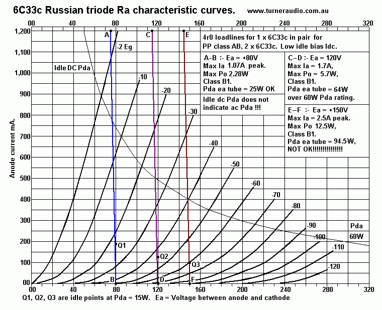
Fig 7 shows three 4r0 loadlines for 3 different Ea, +80V, +120V and +150V. The 4r0 loadline is very nearly
a vertical load line, like a short circuit. Very little Ea change occurs. All loads up to 32r give a similar result,
but max Pda will always be Average Ea x Average Ia pk. The Ia change vs Vg change and hence voltage gain
is a very non linear transfer function where idle Iadc is kept low for class AB action with low % of class A.
What I said for 6AS7 applies to 6C33c.
 
The 6C33c like the 6AS7 has very low grid input resistance if the grid is driven positive when grid begins to draw
current because it is positive with respect to cathode. I cannot recommend use of a cathode follower to try to
force the grid to say +25Vpk. This is likely to reduce reliability even lower than it already is with RL = 4r0 to 32r0.
Russian data sheets indicate grid current beginning at Eg1 = -2V. Just how high peak Ia can rise is not well known
or well publicized, and Ra data curves for 6C33C show max Ia at 1A and curves do not extend further and there
are no Ra curves for high positive values of grid voltage.

Just What is the maximum peak Ia?
See Fig 7 above. If you project the Ra curve for Eg = -2.0V well above the extent of graph and you project the
4r load line from Ea +150V, then the intersection of load line and Eg curve will be where Ia = about 2.5Amps.
Depending on Ea, the Pda rating is easily exceeded. With Ea at = +120V and 4r0 load, Po = 5.7W for 2
tubes. I estimated peak Ia =1.7A, and max Pda = 64W, for each of 2 tubes.

With Ea = +120V and 8r0 load, Po = 9W, 2 tubes, peak Ia is about 1.5A, max Pda = 57W for each tube,
just under Pda rating. Therefore more than 2 x 6C33c are best, and 4 will give 18W with a 4r0 load, without
getting too hot.

I have seen claims at www.audioasylum.com where a guy called Hans said Iapk may be up to 3A,
http://www.audioasylum.com/cgi/t.mpl?f=otl&m=30167
I don't believe such high Iapk is safe. 3Apk gives Po =18W for 4r0 with 2 x 6C33c. If Ea = +150V,
Ia pk = 3A, average Ia = 0.945A, Pda = 133W for each tube. The Pda limit of 60W will be reached far
below the maximum Po level and tubes are likely to overheat and / or arc internally.

Fig 7 shows the curve for Pda = 60W maximum allowed. This curve is for steady state Ea dc x Iadc.
The general rule for conventional design for PP amps indicates class B load line for class AB working should
not become located much above the Pda curve. Allowing the B loadline above indicates signal Pda could be
excessive. With Ea at +150V, the E-F 4 ohm load line is mostly above the 60W Pda line and thus excessive, but
for Ea at +80V the A-B 4r0 load line is mostly under the 60W line. The chosen value of Ea has a huge influence
on reliability.

So far, Ea = +120V looks like the best Ea for OTL. For minimizing cross over distortion the idle Pda could be
15W, so idle Iadc could be 125mAdc. There is an extremely low amount of initial class A before AB begins.
GNFB cannot fully conceal the result of gain change during each wave cycle, and which causes crossover
distortion, mainly 3H.
--------------------------------------------------------------------------------------------------
Class A with SE 6C33c.
The 6C33c gives fabulous music when used with a good output transformer.
Fig 8. 6C33c class A loadline for 382r.
6C33c-Russian-ClassA1-loadline-22-dec-2013.GIF
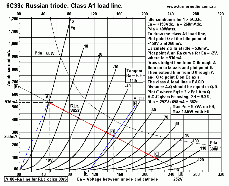
Fig 8 shows the class A1 loadline B-A-Q-C-D = 382r RLa for a single 6C33c. The Q point for operation
was chosen for +150V and 268mAdc because it is a comfortable Q point for 6C33c for class A, idle Pda
= 40W, safely below Pda max rating of 60W. Eg1 = -47V.
Ea swing = -102V for Eg1 swing +45V, and Ea +70V for - 45V.
THD mainly 2H = 100% x 0.5 x ( AQ - QC ) / ( AQ + QC ) = 100% x 0.5 x 32 / 172 = 9.3%.
Va pk-pk = AQ+QC = 172V = 60.8Vrms, Po = 9.68W, without GNFB. With GNFB, THD < 1%,
Va pk-pk = 200Vpk-pk approx, = 70.7Vrms, Po = 13.1W. Other Q points and loads may be chosen
with similar outcome but 382r for the chosen Q point is the load which produces the most class A Po with
fair linearity.

Fig 8 is for a single 6C33c or one of a PP pair for pure class A. The PP pair will act to prevent 2H currents
getting to the output load, but there will be a level of 3H, perhaps 3% at 26W maximum if RLa-a = 764r
for an OPT primary with a CT.

If 2 x 6C33c are in a Series Pair, as in many OTL amps, and each biased and loaded as in Fig 7, the RLa
of both are in parallel so OPT has one winding, and load = 191r. Max Po is the same 26W, and tubes
operate the same way, but with different connection arrangement.

Using 2 x 6C33c in parallel SET will also give 26W in pure class A to RLa 191r. The class A operating Ra
line is the line E-F drawn though Q and is the average tangent line to nearest Ra curves to Q.
The Ra for Q at at +150V and 268mA = 140r. With 2 x 6C33c, the Ra of each are in parallel so Ra = 70r,
and if RL = 191r, DF = 2.73, quite good, and without any loop NFB.

If we avoid the work of drawing load lines on a PC screen, or exercize book, then RLa class A1 load for
maximum output power for many Ea x Ia values :-

Class A1 RLa = ( Ea / Ia ) - ( 2 x Ra ) = ohms r, where Ea and Ia are at idle, and Ra is from tube data sheets,
calculated as R value of straight line from point A to 0V/0mA ( see Fig 7.)

In this case Ra = 48V / 536mA = 89r6.

RLa = 150V / 0.268A - ( 2 x 89r6 ) = 380r. This is fairly close to 382r estimated using the graphical loadline
method of load calculation.

Class A Po max with NFB = 0.48 x Iadc squared x RLa.

Using the above formula gives a table for pure class A1 operation based on a range of Ea and Ia and the data
sheet Ra and for a constant safe idle Pda of 40W.
Table 9. SET class A, PP class A.
Pda at
idle, W
Ea +Volts Ia mAdc RLa
ohms
Po W Effic% DF
40W 150 267 380 13.6
34 2.7
40W 175 228 609 15.2
37 3.8
40W 200 200 840 16.1
40 5.2
40W 225 178 1,102 16.7
41 6.8
Table 9 shows various RLa with various Ea and Ia and Po outcomes.
For more than one 6C33c, used in Parallel SET, or varieties of PP class A1, the Po max can be
multiplied by no of tubes, and RLa or RLa-a re-calculated. For 2 x 6AS7, 2 x 6336, the same
figures can be used where each of the tubes has idle Pda at 20W. Class A action as above is
only possible with an OPT.

Table 10.
6C33c configurations for pure class A1, Idle Pda = 40W, Ea = +175Vdc, Ia = 228mAdc.
Tube configurations.
Ea, Vdc.
Iadc,
mAdc.
Primary
RL
Po, W
Class A1
OPT pri RLa for one SET 6C33c.
175
228
570r
14.7
OPT pri RLa for 2 parallel 6C33c. 175
456
285r
29.4
OPT pri RLa 4 parallel 6C33c.
175
912
142r
58.8
2 x 6C33c, Normal PP OPT, ct to B+
175
456
1,140r
29.4
2 x 6C33c, Series Pair with C to OPT
350
228
285r
29.4
2 x 6C33c, Circlotron OPT, ct to 0V
2 x floating 175
2 x 228 285r
29.4
Table 10 shows how the OPT must change when tube numbers and configuration varies.
Class AB1 and 6C33c.
We must first consider the load lines for Pure Class B1. There  is already a description in Fig 5 for
use with a 4r0 load for OTL amp which shows a near vertical load line with very little Ea swing,
and negligible class A Po, and the function is almost entirely class B1. The issues of overheating
with such low RLa have been addressed.

We must consider sensible values of RLa which won't cause tubes to overheat, and which will not
require a huge amount of GNFB to try correct THD & IMD caused by using RLa that is far too low
for a good hi-fi amp.

Fig 9. 6C33c Class AB loadlines
6C33c-Russian-ClassB1-loadlines-22-dec-2013.GIF
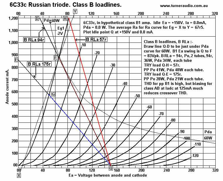
Fig 9 shows how to work out a class B load which will lead you to understand how one 6C33c of a pair
works in class B1. From there, AB1 action should be understood. Each tube of the pair have Iadc set for
0.0mA at idle. No sane designer would really set up 2 output tubes like this because crossover distortion
would be much too high. You can see how the distance between Ra curves "bunch together" at low at Ia
swings less than 200mA. The Ra curves indicate Ra is high and gm is low at low Ia levels, and µ, the product
of gm x Ra is also moderately lower than at bias points well above 0mA dc. The output resistance of the
amp with 2 tubes will be higher at low levels and change during each wave cycle to give an S bend in the
transfer curve.

Fig 9 shows three class B1 RL for each 6C33c in a conventional PP circuit with an OPT or in a Series Pair.
The 3 loads are 57r, 94r, 175r, with idle Ea = +150V, and these RLa are all over 10 times the ohm value
of any speaker. Each tube of the pair will work with the same load for all of each 1/2 wave cycles.
Each tube can only produce power when its signal Va-k reduces when Ia increases due to positive going Vg.
The output transformer or Series Pair connection make it possible to combine the same increase of Ia on
each 1/2 output wave.

If the B RLa = 57r, the nominal RLa-a for 2 tubes + OPT with CT is 4 x 57r = 228r. Even though nominal
RLa-a = 228r, the load each tube sees is 57r for each positive or negative 1/2 wave of Vac. The Va max
on each tube = 68Vpk, so The Va-a max = 2 x 68Vpk = 96Vrms which makes class B Po = 40.4W.
Having RLa lower may increase Po a bit but could easily produce Pda > 60W, and thus cause overheating.
Linearity is poor for all 3 loads shown in class B1. The Rout of amp depends on Ra which varies between
very high during first few W to the Ra max when Ia is highest. The Rout of the B1 amp changes during the
wave cycles which causes high overall THD.
If the 6C33c are biased with Iadc = 125mA, Pda = 19W, and crossover HD is very much reduced, and
change in Ra is much reduced, and THD during first few W becomes quite low. The action becomes class AB.
The maximum betterment for having substantial Iadc at idle is for the highest class B RLa shown as E-G-Q, 175r.
For a normal OPT with CT the RLa-a = 700r. Peak Va-a = 200Vpk = 141.4Vrms giving class AB Po
= 28.5W, and initial class A = 5.5W. Biasing the tubes with Iadc higher than pure class B with no Idc will not
much change the maximum total Po but it will much reduce THD.

For 2 x 6C33c in Series Pair, and for class Ab1, nominal primary OPT RL = 175r. The Va-k = 70.7Vrms of
both tubes is applied in parallel to 175r to make 28.5W AB, and 5.5W class A where each tube has RLa = 350r.

Winding losses vary slightly with the amount of class A and AB Po. For a normal PP OPT with CT for B+,
there is twice the Vac across primary than for Series Pair OPT. The Series pair OPT will have 1/2 the primary
turns wire dia 1.41 greater than for normal PP OPT, using the same core size, to get the same winding losses.

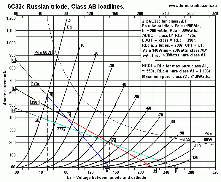
Fig 10. 6C33c Class AB1 and A1 loadlines.
6C33C-Russian-ClassA+AB1-load-lines-dec-2013.gif
Fig 10 shows load line C-B-D-Q-F for good AB1 operation, with each 6C33c biased at 150V x 200mA
for Pda = 30W.
Load line D-Q-F = class A RLa for each tube = 350r.
Load line B-D-A = class B RLa for each tube = 175.
Load line G-Q-I = class A load for maximum possible pure class A1 = 553r.

For class AB1, Tube X and Tube Y can be used with normal OPT with primary RLa-a = 700r, or in a
Series Pair as in OTL with RLa = 175r. The loadlines are the same for either type of output stage configurations.
Tube X is loaded by D-Q-F 350r in class A, Ia pk increases to 2 x Idle Idc at point D, 400mApk. The other
tube Y has Ia reduce to 0.0mA and Ia cuts off at point F. Tube X is then the only tube connected to the load and
the tubes cease to share their class A load. The load for X changes from 350r to 175r and Ia increases from D
to B, along the lower load of 175r.

The displayed change of RLa during each wave 1/2 cycle does not follow the exact straight line analysis because
the triodes do not have a sharp cut off character. In fact, the load of each tube in class AB is a curved line with
value of 350r at Q, then curving to become 175r between D and B, and this gradual change of loading in triode
class AB amps creates much less harmonic products than would occur if the tubes were sharp cut off types which
more closely followed the straight line analysis.

The mathematics for H production is totally impossible to work out for nearly everyone including myself.
But it is safe for me to say AB triodes sound better with less HD products than other pentodes or mosfets when
compared under similar A and AB operation. But the load lines predict circuit behaviour remarkably well.

Lowest THD is for pure class A PP where the RLa for each tube is for maximum class A, perhaps 2% for 6C33c
just under clipping. The THD of above AB Po may be 3.5%. But at low levels < 2W, the THD difference is not
much and the sound is good.

OPT with CT, RLa-a = 700r : 5r0, TR 11.85 : 1.
OPT for Series Pair RLa//RLa = 175r : 5r0, TR = 5.92 : 1.

In Fig 10, I have included a loadline H-G-Q-I = 553r for pure class A loading. The RLa-a for 2 tubes would
be 1,106r for normal OPT with CT, or 277r for Series Pair. With Iadc at 0.2A, Po max for each tube = Each
tube will give up to 10.9W class A, so the PP pair make 21.8W, ( with NFB ).

The letters used to number load lines in Figs 7,8,9 are different because it was difficult to use same lettering
in all 3 Figs. If you can understand each Fig 6,7,8, then you should be able to draw class A and AB load lines
from start to finish on the on the one sheet.

I conclude ideal OPT for normal class AB = 700r : 5r0, or 175r : 5r0 for Series Pair. Any speaker Z above
3r0 will be be driven well.

One might be tempted to use a toroidal 160VA PT with 2 x 117V primaries in series and 2 x 18V parallel secs.
TR = 13.0 : 1, Mains load = 342r, sec load = 2r0. But with wanted primary Va-a = 140Vrms, Bac = 1.2Tesla
at 36Hz, and is too high. The mains PT will give 700r : 4r1, about twice the ohm loads for PT, so Rw losses
will be about 1/2 for mains use, about 4%, OK. Using higher VA PT will not reduce Fsat at 36Hz, although
winding losses will be lower be lower. The same PT could have sec in series for TR = 6.5 :1 for mains load of
342r : 8r0. A Series Pair of 6C33c require load of 175r, so PT gives 175r : 4r0, and winding losses are twice
the 8% normal losses of PT, say 16%. The Vo output = 70Vrms so Bac = 1.2Tesla at 18Hz and is OK.
The use of a 320VA PT will have same Fsat, but its mains loads will be close to what is wanted by the amp,
and the higher VA PT has less Rw losses than 160VA, so expect 6%, and OK.

CORRECT ANALYSIS is needed for whatever toroidal PT one is tempted to use with vacuum tubes, to
avoid paying a huge price to someone for a special OPT.

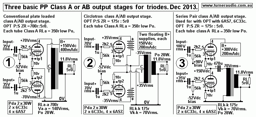
Fig 11. Three basic output stages for 2 x 6C33c, or 4 x 6AS7.
Three-PP-triode-output-configs-dec-2013.GIF
Fig 11 shows :-
1, Conventional PP with OPT with CT,
2, Circlotron,
3, Series Pair.
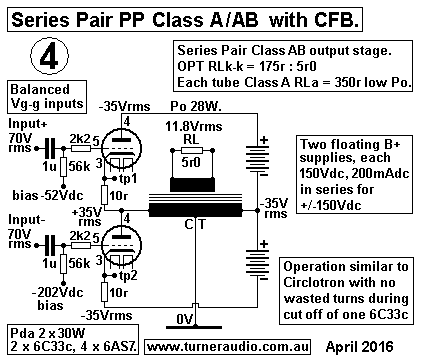
Fig 12 shows :-
4, Series Pair with 50% CFB.
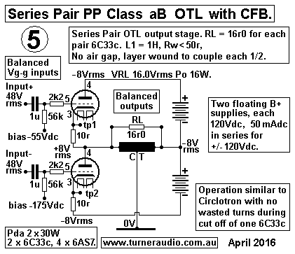
Fig 13 shows :-
5, Series Pair class AB OTL with CFB.

Most common is No 1, with 2 triodes in traditional PP. But the Circlotron and Series Pair have been used by very
few makers of tube amps. Of the few using the Circlotron, most have been in OTL amps. But Electrovoice did make
a Circlotron in 1950s with 2 x 6V6 for 20W class AB1 output. Triode-One in Canada made a stereo amp with
2 x 20W from 6550 in triode Circlotron, then they went broke. The multiple floating B+ rails was the main cost
difficulty, and screened HT windings are needed. I serviced a Triode-One amp, and found it worked just fine.

I have not shown the McIntosh connection. This is a variation on No1 where the primary winding is divided into
two equal windings of 1/2 the total P turns, each with CT, with one at 0V potential for CFB winding and other at
B+ potential for anode winding. This allows 1/2 Va-k to be fed back at each cathode, for ß = 0.5. The tubes have
a similar amount of local CFB as the circlotron. The two half primaries are wound bifilar, for very tight magnetic
coupling of each half primary. Only McIntosh went to such a huge amount of bother to make their OPT.
Use of 6550 or KT88 meant that the Ea of +450V could safely be applied to screens, and tubes worked in beam
tetrode mode with 50% local NFB. The max Vg drive on each side of PP circuit could be 150Vrms.
McIntosh were the first to get 50W from a pair of old 6L6 in near class B in 1949 and with high total GNFB they
got good measurements. Nobody I know has ever altered a McIntosh to work in triode mode, or to have screens
taken to a fixed Eg2 but this is possible, and then tubes work in UL with 50% screen taps and with 50% local CFB.

But here I am dealing with TRIODES, with no screens, and with low µ.

The basics here are to allow those to explore use of low µ and low Ra triodes which have lower Va-k and thus
become more easily usable in circlotron or series pair mode. One 6C33c in SET with class A load has Va-k
only 70Vrms in Fig 9,10. The 6C33c needs Vg-k drive about 36Vrms, gain is up to 1.9, so 6C33c is no more
difficult to drive than any KT88,6550,EL34,6L6. 

In Circlotron, 1/2 Va-k appears at anode and cathode, +/-35Vrms, and Vg-k = 35Vrms, so Vg-0V = +/-70Vrms
at each grid each side of PP circuit. This is all quite easy to do.

The Series Pair (SP) No 2 has the same OPT as Circlotron, 175r : 5r0, but there is no need for a CT, and one
end of primary is to 0V, and tube output at live end = 70Vrms. The top tube needs Vg-0V = 105Vrms and
bottom tube needs Vg-0V = 35Vrms, and the main difficulty with SP is the generation of the unequal Vg-0V
drives which keep Vg-k exactly the same although oppositely phased for PP.

To make such high grid drive Vac with low THD with wide bandwidth and low circuit resistance is a challenge,
but not impossible, mainly because the signal current needed is fairly low. EL34 or EL84 in triode mode make
the world's best drivers of many other output tubes such as 845, or where a lot of CFB is used, and where Vac
may exceed 140Vrms.

Fig 12. Series pair with CFB.
6C33c-Series-Pair-4-PP+CFB-bal-drive-OPT-april-2016.GIF
The basic Series Pair can use an OPT exactly the same as the circlotron, ie, 175r : 5r0, AND with same CT.
Fig 12 shows the CT taken to 0V. The two floating 150V B+ supplies are connected in series, and the CT of
the Vdc connected to one end of OPT, and this arrangement makes the stage work just the same as circlotron,
but with series tubes, and the input is balanced and therefore MUCH easier to provide by use of an LTP triode
driver stage.

Fig 13. Series Pair class AB OTL with CFB.
6C33c-Series-Pair-5-PP+CFB-bal-drive-OTL-april-2016.GIF
Here is another basic Series Pair used for plain old OTL, shown here to compare outcome with Fig 12.
The OPT has been replaced by a 1H choke with CT so a complicated OPT is not needed. Ideally,
the choke is layer wound with even number of layers, with alternate layers in each half winding so that both
halves are tightly magnetically coupled. There is no need for bifilar winding with high shunt C between half
windings to get an exact CT. This is a small choke, and might use E&I core T25 x S25, no gap, wire about
0.5mm dia. The Output RL is connected to across each end of choke, and the output Vac is balanced, and
at 0V potential with CT taken to 0V. The PSU is a +240Vdc supply with CT to give +/- 120Vdc as in 11.
Balanced grid input is needed, like a circlotron.

I show RL = 16r0, which means class A load to each 6C33c is 32r, but the amount of class A Po < 0.4W,
negligible, and each 6C33c sees 16r0 most of the time. The result is that Po max for 16r0 is possibly 16W,
only about 1/2 what can be had from use of OPT, and THD is atrocious. The reduction of THD by the 50%
CFB is negligible, but the purpose of the whole arrangement is to make the drive to each grid equal which
can come from an LTP with a pair of triodes in an ECC99.

KT120, KT88, EL34, 6L6 and 300B in Series Pair mode is so rare we might say nobody has ever done it
because a high supply B+ is needed, and there is no sonic betterment.

The cold hard fact is that ordinary plate loaded triode output stages are very good things especially in class
AB where up to 1/2 the maximum AB Po is available as pure class A for initial Po. Such triode operation has
been a kind of gold standard since 1925.

Pursuing Series Pair operation is not entirely silly. There is a ""simple"" solution to achieving the high grid
drive Vac, and which takes care of the drive imbalance.

Fig 14. 30W class AB1 amp Series Pair 6C33c plus IST.
6C33c-28W-AB1-Series-PP-CG7-EL34-IST-OPT-dec-2013.gif
Fig 14 has SET V1 6CG7 input for some overall voltage gain of 15, and feeds V2 EL34
SET driver, gain = 9. V2 RLa is primary of a 10k:10k IST and V2 anode load = effective
Lp // R16 // R17, 50k. EL34 Va = 37Vrms, which drives the bottom V4 6C33c grid g1.
IST secondary has one end connected to V3+V4 output with 70Vrms. There is 37Vrms
across the secondary and it adds to the 70Vrms to give 107Vrms drive to top V3 6C33c grid.
The Vac of transformer are arranged to give opposite phase drive to each V3+4, and the
Vg-k drive remains always constant and the same for both V3+4.
Drive to EL34 is only 4.2Vrms to make 37Vrms at anode, so EL34 THD is very low with the
high ohm value of its RL, while Ra of EL34 is only 1k4, so it is a low Z signal source and
bandwidth will be wide enough. Hammond make a suitable 10k:10k IST, but better types
may be available, but there must be an air gapped core for the Idc, and Fsat should
be less than 30Hz for 50Vrms across each winding.

There is no local NFB in output stage. Ra of each 6C33c, about 175r at the Q point
shown in Fig 10. Rout without GNFB at V3+4 is the parallel Ra of both 6C33c, about 87r.
At OPT sec the Rout = Ra//Ra / ZR = 97 / 35 = 2r5. If the output load = 5r0, the
damping factor = 2.0. The 14dB GNFB will reduce Rout to about 0r4, for DF > 10 = OK.

The problems of having both IST and OPT in an amp are the extra LF and HF poles
introduced to the open loop gain character so that application of GNFB is will be likely
to cause LF & HF oscillations. I suggest the amount of GNFB be kept kept below 15dB,
because this is usually enough in a triode amp where the output stage already DF
above 1.0, and low THD/IMD. Usually, unconditional stability is achieved with open
loop gain shelving R+C networks and stable closed loop bandwidth of 10Hz to 50kHz
is achieved with a pure R load, and square wave over shoot with an C load between
0.1u and 1.0u is not excessive with no R. GNFB feed could be applied from the single
output at V3+4 and fed back to an input stage without inclusion of the OPT sec leakage
inductance. But this would require V1 6CG7 set up as a LTP to get the required relative
phasing of input and NFB signals.

C14 = 2 x 470uF in parallel to couple V3+4 output to OPT primary. If primary RL = 175r,
then LF pole is just under 1Hz, probably OK, and unlikely to cause oscillations if the LF
gain shelving is correct. After building so many amps of very different types, I see no
reason why the Series Pair with ST & OPT cannot give good music.

Fig 15. 30W class AB1 amp Series Pair 6C33c plus bootstrapped CPI.
6C33c-28W-AB1-Series-PP-CG7-EL84-EL34cpi-OPT-dec-2013.gif
Fig 15 looks like most other OTL amps except for the included OPT. V1 6CG7 is SET input and in
generic differential mode. V2 EL84 triode is SET gain tube to feed V3 EL34 concertina phase inverter
to make the two phases of g1 drive of +107Vrms and -37Vrms to V4+V5 6C33c. The anode R19
load is "bootstrapped" via C9 100uF to V5+6 output. The current in R19 3k3 is same as in R20 3k3,
so that opposite phases are produced, but the bootstrapping makes Va drive to V5 g1 much higher, and
the two output tubes then get the same Vg-k drive Vac for all conditions. Value of R18 is not critical,
and is a negligible load for V5+6. But with so many series R, the B+ for the V4 driver should be above
+500Vdc. Fig 14 is based on 1950s design by Mr Futterman. I did not invent it.

Without any IST, Fig 15 should be easier to stabilize with GNFB from OPT sec fed back to V1 cathode.

The Series Pair could be set up with "split" output B+ and B- rails of +/-150Vdc. But this introduces
problems of LF stability because the -150Vdc rail must be extremely quiet and free of LF noise, and I can't
recommend anyone do it, even though I did do this in my SE55 with a pair of SET parallel 845, with
+/-630Vdc, to lower the Vdc stress on OPT insulation etc. Here, the Vdc used is much lower, so no need
for a split rail. Even when split +/- rails are used, and with output taken from tubes to 0V direct, as in some
OTL, there will always be some minor +/-Vdc to the load. If a tube fails, there could be an amp or two fed
to a speaker or to primary of an OPT which is going to spoil the party. With Output from V5+6 at +150Vdc
or =120Vdc, the Vdc could rise to +300V if bottom tube goes open, or falls to 0V if bottom tube shorts,
either failure mode is OK if the C12 caps are rated for 350Vdc.

Many early SS amps used a Series Pair of the same NPN bjt, aka known as Quasi Complementary Pair.
It was usual to have a single rail of say +45Vdc, so that Vout swing was +/- 20Vpk, or 14Vrms, able to
make 49W into 4r0, and a coupling cap between fragile 1967 device output and speaker was essential.
Sugden has made a range of PP Series Pair amps which still have the same basic topology as in 1969.
They make a lot of class A power before AB commences. I found heatsink is totally obnoxious, with not
enough fin area, and with fins from body running horizontally, so the air flow is seriously obstructed.
The class A Sugden runs hot, and all inside the box gets too hot, causing oxidation of all naked metal on
PCB tracks et all. I repaired and serviced these horrid amps so I know how bad they are.
There are better techniques.

For many old amps with series connected transistors aka bjts there is a single +Vdc rail, often +47Vdc.
The output is from join of top bjt emitter and bottom bjt collector which is at about +23Vdc. The
output often used a 2,200uF x 50Vdc electro cap to the speaker load at 0V, and if speaker load = 8r0,
the total impedance of load was about 11r0 at 9Hz. Vdc could not flow to a speaker, and when these old
had a bjt failure due to a shorted load or speaker cable, the speaker did not become directly connected to
+47Vdc which destroys the bass voice coil in seconds. But the low value 2k2 could over heat before
causing bjt failure and they can become a short circuit which then directly connects speaker to +23Vdc
also causes voice coil to fry. Nearly all amps like this did not have a protection circuit to turn off the amp
at mains as soon as more than 0.25Vdc appeard at amp output.
Sugden amps have a 10,000 uF electro cap which probably would not overheat of load is a short circuit
because the cap current rating is high enough, maybe 10Amps, so the bjts will definitely oveheat and die
before cap fails. The 10,000uF has a lower pole at 4Hz with a 4r0 load.
In above amp, I show x 2 x 6C33c coupled with 940uF to primary of OPT at 0V, and the OPT secondary
is at 0V and there is no way Vdc could ever be applied to a voice coil.

Fig 16.30W class AB1 amp Series Pair 6C33c plus Technics drive stage.
6C33c-28W-Series-PP-AB1+OPT+TechnicsPI-amp-dec-2013.GIF
Fig 16 has an almost identical schematic to Fig 15. BUT, Fig 16 has a Technics driver stage to Series
Pair OTL output stage of 2 x 6C33c and an OPT. V3 EL34 is a concertina phase inverter with
bootstrapping from V4+V5 Vo to R19 cathode load of V3. This makes BOTH 6C33c work as parallel
cathode followers with Rout of about 31r. This is 1/3 of the Rout for Fig 15, and THD/IMD is also
reduced locally by about -6dB. The price paid for such local improvement is the Vg-0V applied to V3
EL34 grid is increased from 53Vrms to 123Vrms. This means the V2 EL84 gain stage can make good
use of a choke + R for Idc anode feed, and thus total anode RL > 100k, so EL84 triode gain is maybe
18+, and THD < 2% at 123Vrms.

The OPT for 175r : 5r has no Idc flow and has no air gap. It may have a CT which is not connected to
anything.

The 14dB GNFB might be OK if the circuit is made as shown, but there is a radical alternative never used
by anyone else. Instead of all that GNFB, it is possible to remove R14a 220r, and feed Idc to V2 g2 via
about 68k from +510V rail. Then g2 is bypassed to V4+5 Vo +70Vrms. The g2 screen of V2 EL84 acts as
a grid to give gain of about 10x because the anode RL > 100k. So any THD of output stage and EL34 is fed
back to V2 g2, and FB correction factor is about 20dB. It is a lot of NFB, but safe because the loop does
not include the OPT and only encloses 3 amp stages. This form of g2 NFB worked well in an a Hybrid amp
I built at solidstateamps5+tube-input.html It is about 5/6 down the page.
If such NFB is used, the GNFB should be much reduced to perhaps 6dB, but then the high Vac and highish
THD of produced by V2 EL84 may go uncorrected. I have NOT tested the idea, and Fig 15 schematic as
shown is probably the better option for most ppl who struggle for years trying to make anything else work
properly and with complete stability.

The Technics drive circuit reduces Rout by 1/3, and with the 14dB GNFB, the reduction of Rout is 1/5, so
Rout with Technics is almost too low, and GNFB can probably be reduced to 10dB for a good result, and
easier stability. Don't ask me which of the amps in Fig 15 or Fig 16 will sound the best.

The Technics FB circuit can use a 10k ; 10k IST normally meant for driving an SET output tube by driver
triode and to avoid using capacitor coupling. But one winding is used instead of EL34 anode R18, and the
other is used instead of cathode R19, and this allows the +510V to be reduced to about +400Vdc.
R20 can be reduced to 2k2, so B+ could even be lower. But having the IST means much more attention
has to be given to stability with GNFB.

Fig 17. 30W class AB amp with normal PP OPT with CT to B+ for 2 x 6C33c.
6C33c-30W-PP-normal-AB1-amp-dec-2013.GIF
Fig 17 has 2 x 6C33c used in a "Normal PP amp" configuration for class AB1. I expect nobody
will try to build this, which is probably THE BEST way to use 2 x 6C33c ( or a quad of 6AS7 ).
But you need a 60W OPT for 700r : 5r to suit most expected loads, and nobody I know makes
such an OPT for PP, with CT.

Fig 18. 30W class AB Circlotron with 2 x + OPT.
6C33c-30W-Circlotron-amp-dec-2013.GIF
Fig 18 has 2 x 6C33c in a Circlotron. It means the OPT with a CT can have one winding with half the turns
of the 700r OPT used in Fig 15. The primary load is 175r. Each 6C33c works in parallel during class A
action and has RLa = 350r. The OPT may be exactly the same as for the Series Pair connected 6C33c in
Fig 16, but with CT taken to 0V. There is no air gap, and Iadc of each tube should be equal within +/-5%.

Transformer cores for all conventional PP amps should have equal (balanced) Idc flows in opposite
directions in each half of their primary with CT. In a Circlotron, the Idc of each 6C33c flows in opposite
directions across the whole primary winding. This may seem difficult to understand, like walking forward
and backward at the same time but common sense does not apply in all electronics. With two equal dc
currents flowing in opposite directions, there is zero Idc flow in the winding, and no dc magnetization of the
core. If there is more Idc in one direction than the other, then you have the difference between the two
currents flowing in one direction, the net Idc, and thus will cause dc magnetization, just like in any electro
magnet. In the real world, exact balance is not possible, and there is a big chance of some Idc imbalance
in the OPT, thus causing DC core saturation with a small net Idc, say 5% of either Idc for 2 tubes.
The the core permeability ( µ ) should be kept below 3,000 by partial air gapping of the E&I laminations,
or a tiny air gap between double OO pattern with C-cores.

I would never use a toroidal OPT where there are two Idc flows which must be balanced.
Toroidal cores are a spiral wound thin strip of GOSS material with no cuts or joins in the direction of grain
and have max µ = 40,000. Bdc, ie, dc magnetization in Tesla is directly proportional to u x Idc, and a small
Idc imbalance will saturate the core easily and ruin music. I recall Plitron have made toroidal OPTs with
a cut which is set to a specific gap to suit SE transformers with heavy DC magnetization, but they are
very expensive. All mains PTs do not have any air gap so µ is too high for DC imbalance.

However, the OPT as shown in Fig 17 could be replaced with a 2H choke wound on E&I core, with CT
to 0V, and µ = 2,500, to obtain a high enough inductance and freedom from saturation at LF or by
unbalanced Idc. A toroidal or PP OPT with no gap can be coupled in parallel to choke but with
1,000uF at each primary end to keep any Idc out, but allow signal currents to flow. But that means
two heavy iron wound items instead of one, and you may as well just make a good OPT with E&I
lams or C-cores. You will find that a 700r : 5r OPT is far easier to wind than for 7,000r : 5r.

The worry about high core permeability can be reduced if the Idc in each 6C33 is actively balanced by
a balance pot, shown as VR1, 10k, in Fig 17. In other amps I made, eg 5050, I used fixed bias, but
with balance pot, and two LEDs for each channel to show the balance status, and this method lasts
very well, and was user friendly, and indicates when tubes become unbalanced or when something
else is wrong with the amp.

Fig 19. 29W SET with 2 x 6C33c, screen NFB to EL34 driver, GNFB, OPT with CFB.
6c33c-29W-PSET-amp+g2FB+CFB-dec-2013.GIF 
Fig 19 shows 2 x 6C33c in parallel SET to work with an almost "normal" SE OPT with air gapped
core because 536mAdc flows in primary windings and is not balanced. The idle condition for each
6C33c is shown in Fig 8 for class A. Each 6C33c has Ea +150V x Iadc 268mAdc, idle Pda = 40W.
RLa = 380r. For the 2 x 6C33c in parallel, Va-k = 74Vrms into OPT primary RL = 190r, and Vgk =
+/- 45Vpk = 32Vrms.
This means open loop gain, OLG, of 6C33c = 74V / 32V = 2.3. The Va-k is split in equal halves with
34Vrms at both anode and cathode, opposite phase, so 1/2 Va-k is feedback in series with Vgk, ie,
ß = 0.5, and Vg-0V = 34V + 32V = 66Vrms. Closed loop gain CLG = 74V / 66V = 1.1, so gain
reduction due to local FB = x 0.47, ie, about -6dB. The Ra of both tubes in parallel with no FB = 70r.
Ra with local CFB = 30r. The DF without any other NFB = RLa / Ra = 190r / 30r = 6.33, a very good
figure without any reliance on GNFB.

The maximum -66Vrms drive to output grids is produced by EL34 in SE pentode mode. Its gain is
maximized by use of L1 60H choke + R13 6k8 between anode and +420Vdc rail. The screen of
EL34 is fed Idc via R15 39k. Screen is bypassed with C7a 47u to the cathodes of 6C33c where
there is -37Vrms. So the EL34 is working like an output tube where there is about 50% ultralinear
taps, and its maximum pentode gain of about 120 is reduced to 12.9 or close to the triode µ of 9.
The EL34 is thus made to work more linearly than pentode, and in fact as linearly as triode with a
high RLa many times the triode Ra value.

Any THD voltage can be nominated as +Vdn between anode and cathode of 6C33c. At anode, you
would measure +0.5Vdn, and at cathode -0.5Vdn, with respect to 0V. Therefore -0.5Vdn is applied to
EL34 screen and amplified by screen gain of at least 8. The screen has gm of at least 0.28mA/V, the
gain = gm x RLa // Ra = 0.28 x 28.5k = 8.0. So the -0.5Vdn at screen is amplified to become +4Vdn
at EL34 anode and is applied to at 6C33c grids. The 6C33c gain between grid and anode or cathode
= 0.515, so there is -2.06Vdn at anode, +2.06Vdn at cathode. But we measure 0.5Vdn.
How can this be? It is because without the screen FB loop, the 6C33c will produce 2.06Vdn +0.5Vdn
at both cathode and anode, ie, 5.12Vdn total THD relative to Va-k without NFB.

The measured Vdn at anode or cathode of 6C33c is the reduced Vdn after NFB has been applied.
Here, the THD reduction is from 5.1 to 1.0, about -13dB. The text in Fig 18 says NFB = 12dB,
a conservative figure. This 12dB adds to the 6dB of local CFB in output stage so the 9% of THD
without FB at 28W is reduced to about 1%. This will sound fine if the average power on each channel
is 1W, when THD = 0.1% approx. I show about 10dB GNFB as well, so expect 0.03% THD at 1W,
and 0.3% at 28W. It is higher THD than any P amp, but quite acceptable.

I have calculatedTHD from the data curves, and not from a real tube in a real amp. THD may be a bit
more or less in the real world. The driver tube in this case is an EL34 with choke plus R loading at
anode and its 2H is low, and will not much cancel 2H produced by output tubes.
I doubt anyone will find an available OPT for 190r : 5r0 or with loads within +/-20%.

The OPTs in this page are far from "normal", they belong to type known as Unobtanium.
They all must be carefully layer wound by an expert after being designed by another expert.
The experts should follow all my logic flow at SE OPT calcs and PP OPT calcs.

I show Cathode Biasing on each 6C33c with R18+R22 = 180r, 40W, using say 4 x 180r x 10W in
series / parallel to get 180r x 40W. This Rk value may need slight trimming to adjust Ek to whatever it
must be to get the product of Iadc x Ea-k = 40W. But with 180r and 268mAdc, PdR = 12.9W and
there are a pair so there is about 26W of heat which must not be produced under any chassis and the
Rk should be bolted to a heatsink with total surface area of 1,000 sq.cm above the chassis and away
rom tubes or caps etc. Not many ppl get exactly the same B+ as schematic or calculations dictate.
The aim is to obtain tube idle Pda = 40W with whatever B+ you have which means varying Iadc by
say +/- 10% to suit the B+ and get Pda = 40W.

The OPT also influences design. The 190r : 5r0 ZR = 38 : 1, and it may not be available but you might
find something with primary RL between 150r and 230r : 4r0, 8r0. 150r : 4r0 has ZR 37.5 : 1 and is
OK and you could use Ea = +140Vdc and Ia = 285mAdc. 230r : 4r0 has ZR 57.5 and Ea may have
to be raised to +170Vdc with Ia = 235mAdc. The 230r : 8r0 has ZR 28.8 : 1, a 4r0 load makes tube
load 115r, much too low. RLa for one 6C33c = ( Ea / Ia )  - ( 2 x Ra ).
To allow for B+ variation between +140Vdc and +240Vdc, the HT winding on PT must have
maximum Vac of 180Vrms and have taps for 165V, 150V, 145V, 130V, 115V.

If ever the 6C33c conduct more than about 1Adc, slow blow 0.75A fuses should blow. TP1+TP2 are
test points taken to an active protection circuit found elsewhere in this site. If Idc to either 6C33c rises
above 350mAdc, Ek would rise from say 48Vdc to 63Vdc which is enough V change to send a signal
to a protection circuit to turn off the amp.

The Rk = 180r will give fairly good regulation of Iadc and equalize the Idc of both 6C33c even if mains
Vac varies by say +/-10%, which is more than I have ever seen.

Distortion can be estimated from the graph of Fig 7 where the 380r class A loadline is shown for one 6C33c.
For Eg change of -47V to -2V, Ea change = +150V to + 48V, ie, -102V.
For Eg change of -47V to -92V, Ea change = +150V to +220V, ie, + 70V.
This means the Ea swings for maximum linear Eg1 swing of +/-47V
are 102V and 70V, Ea Vpk-pk = 102V + 70V = 172V, and the difference
between the swings = 32V.
2H % = 100% x ( 0.5 x difference between +/- Ea swings ) / Sum of Ea swings = 100% x 0.5 x 32 / 172
= 9.3%. The THD in both tubes will be about the same and for the 27W level from both tubes.

Fig 20. 29W SET with 2 x 6C33c and GNFB to 6DJ8 input.
6c33c-29W-PSET-amp-dec-2013.GIF
Fig 20 is a simple SET amp with 3 stages, basically similar to many seen elsewhere on the Internet.
V1 6DJ8 is input amp with gain = 26 and feeds V2 EL34 in triode with gain = 9 which drives 2 parallel
6C33c. The EL34 triode driver has a fair amount of gain, but low Ra of about 1k4 thus has very wide
bandwidth. This technical feature does not fully explain why a power tube used for a driver sounds so well.
6BL7, EL84 and EL86 or a paralleled ECC99 also work well. Builders of this circuit may find it easier to
stabilize with only one GNFB loop.

I don't have time to include all OPT details but I am sure the Clever Men among those reading will find out
all about how to make a decent SE OPT at my other pages.

For those pursuing the challenge of OPT winding or acquisition, here is a guide:-
Table 11.
Amp mode
Idc
Bac
Tesla
F sat
Hz
Rw loss %
maximum
Pri RL
ohms r
Sec RL
ohms r
ZR
TR
Vrms
Prim
Po
W
Series Pair
2 x 6C33c
4 x 6AS7
zero
1.2
20
 8%
175r
5
35
5.9
70
28
AB
Series Pair
4 x 6C33c,
8 x 6AS7
zero
1.2
20
8%
88r
5
17.5
4.2
70
56
AB
Normal PP
OPT with CT
balanced 1.2
20
8%
700r
5
140
11.8
140
28
AB
Normal PP
OPT with CT
balanced 1,2
20
8%
350r
5
70
8.4
140
56
AB
Circlotron
2 x 6C33c,
4 x 6AS7
balanced
1.2
20
8%
175r
5
35
5.9
70
28
AB
Circlotron
4 x 6C33c,
8 x 6AS7
balanced
1.2
20
8%
88r
5
17.5
4.2
70
56
AB
SET 2 x 6C33c
4 x 6AS7 
536mA
0.6
20
8%
190r
5
38
6.2
74
28
A
SET 4 x 6C33c
8 x 6AS7
1,072
mA
0.6
20
8%
95r
5
19
4.4
74
56
A
 thought
needed 
for
any
success
 if
you
dare
!
!
!
I hope I have given most ppl something to think about before they rush to buy an OTL amp,
or to make one,and I hope you can see that 6AS7 and 6C33c can be used with OPTs with far less
wasted heat, less tubes, more audio power and better sounding music. Happy listening.

Fig 21. Russian 6C33c curves for anyone wanting to draw their own loadlines.
6C33c-Russian-data-Ra-curves.gif
This .gif image can be copied to your tube data folder and used to draw your own load lines
or printed for use with pencil, paper and a ruler, just like the engineers did in 1955.
-----------------------------------------------------------------------------------------------
Definitions of terms used here :-
Ohm's Law.
R is resistance in ohms, r, and R = V / I where V is Vac or Vdc applied across R, and
I is amps of current flowing through R as a result of applied V.

RL is Resistance Load, which is the resistance of a wire or manufactured resistor used
to provide a load in ohms for active devices such as vacuum tubes or solid state which
produce a change of current to to liberate power in load as heat, or to make other forms
of energy such as motion in motors and usually measured in Watts, W.
RLdc = load between a DC supply rail and active device which changes current.
RLa = load for ac/dc power produced by an anode.
RLa-a = load for two push-pull anodes of two tubes producing opposite phased Vac to
each end of RLa-a, the resistance between 2 anodes.

P is the symbol of power is in the form of heat or other power measured in Watts and
calculated P = V x I,or P = V squared / or P = I squared / R.
Po = power output,
Pin = power input.

Efficiency % of power generating system = 100% x Power at system output / Power input from PSU.
R loss% = the percentage of input power wasted as heat in any series resistance between
a Vac source and power producing resistance load, eg the wire resistance in a transformer,
known as Rw.

Power Loss fraction = Loss R / ( RL + Loss R ) = P lost / ( P input + P lost ).
Example, Rw = 2r0, RL = 20r0. Loss fraction = 2 / ( 20 + 2 ) = 0.0909.
R loss % = loss fraction in %, eg 9.09% for above.
If loss fraction is known, and RL, then the series loss R calculated = R Loss
= RL x Loss Fraction / ( 1 - Loss Fraction )
Example, Rw % loss = 9.0909% = loss fraction 0.0909, RL = 20r.
Rw = 20 x 0.0909 / ( 1 - 0.0909 ) = 1.818 / 0.9091 = 1.99978, ie, 2r0.
Rough calculations are often made, if loss = 9%, we calculated Rw 1.8r, but that is 11% WRONG.

L = inductance in Henrys, millihenrys, mH, or millionths of a Henry, uH of any known conductor or
coil without inclusion of any resistance or capacitance between 2 points.
C = capacitance in Farads, unit = F, measured between 2 points without any R or L present.
uF = micro Farad = millionth of Farads,
nF = nano Farad = thousanth of uF,
pF = pico Farad = millionths of uF.

Lp = primary inductance of a primary winding on transformer.
Lsec = secondary inductance of a secondary winding on transformer.
LL = leakage inductance between two coils / windings where they share the same magnetic field.

X is Reactance in ohms for either pure L or pure C. The ohm value is only valid for one sine wave frequency.
XC = Reactance ohm value of pure C.
XC = 1,000,000 / ( 2 x pye x Frequency in Hertz x C in uF ) = 159,000 / ( F x CuF ) ohms, or r.
Hertz, Hz = frequency measured in cycles per second,
kHz = thousands of cycles per second,
MHz = millions of cycles per second,

XL = Reactance ohm value of pure L.
XL = 2 x pye x F in Hertz x L in Henrys = 6.28 x F x L ohms. ( pye = 22/7 = 3.4129 ).

Ra = dynamic anode resistance on ohms. Eg, the measured resistance between 0V and anode of EL34 in
triode mode with Ia = 25mAdc and with fixed grid bias and fed with Idc to anode from CCS from B+ may
measure 1,400ohms, 1k4. This does not mean the tube works just like a 1k4 resistor. In pentode mode
with fixed Eg2 and fixed grid bias the Ra measured could be 40k and this does not mean the Ra is equal to
a 40k resistor. The measured Ra is the effect of anode transconductance on electron flow, and the
Ra = 1 / anode gm.

µ = amplification factor of a vacuum tube = V change at anode / V change at grid where the tube anode load
= CCS, so that anode current remains constant although both Va and Vg change.
gm = device transconductance in A/V or mA/V, where a Vac or Vdc is applied across any two circuit
points to produce a current change.
Example, +1V change between grid and cathode cause +5mA change of anode current between anode
and cathode. gm = 0.005A / IV = 5mA per 1V change = 5mA/V.
For all vacuum tubes and for different values of Ea and Ia, the Ra, gm and µ all vary, but for any single Ea and
Ia condition chosen, and for minute Ea and Ia changes, the 3 parameters are related to give µ = gm x Ra.
If two parameters are known, the remaining one may be calculated.

µ = also means iron core permeability, the number of times the inductance of an air cored coil increases when
a magnetic core material is used to make a loop which passes through the coil winding. Core materials can be
many different types including iron, Cobalt, Nickel, etc, etc, and the µ may vary widely depending on Frequency
of applied Vac to coil, or to the level of Vac. Context of µ must be remembered.

Rg = dynamic resistance to a tube grid or fet gate, sometimes used to nominate resistance biasing a grid of
gate, depends on context.
Rd = dynamic drain resistance of FET device.
Rk = output dynamic resistance at a cathode, or can be series R from cathode to 0V or other, depends on context.
Re = dynamic emitter resistance at bjt.
Rs = dynamic source resistance at FET device.
Rb = dynamic base input resistance at bjt.

Z = impedance, measured or nominated in ohms, r, between any 2 circuit points and where any possible
combination of R, L or C may be connected together, but not connected to any external 3rd connection
point. Such circuits with R+L+C are called impedance networks. The Z of such networks is dependent
on frequency of the sine wave Vac applied across the two circuit points. The calculation of network Z at
any given F with more than one R and L and C can be almost impossible to work out with formulas and
s best worked by use of applied software and PC, although simple R+C and L+R networks can be easily
calculated. But without computing, an approximate estimation of Z may be made and values trimmed by
measurement trials until wanted F response and Z is obtained.
---------------------------------------------------------------------------------------------
Z of network R in series with C :-
Z ( R + C) = square root of ( XC squared + R squared ) in ohms, r, where R is ohms, r, and XC is
reactance C in ohms, r, has been calculated for a desired F.


Similarly,


Z of network R in series with L :-
Z ( R + L ) =  square root of ( R squared + XL squared ) in ohms, r, where R is ohms, r, XL is
reactance L in ohms, r, calculated for a desired F.

---------------------------------------------------------------------------------------------
Z of network R parallel to L :-
Z ( R // L ) = 1 / square root of ( 1 / R squared + 1 / XL squared ) ohms, r, where R is ohms, r, and XL
is reactance L in ohms, r, calculated for a desired F.

Simiarly,

Z of network R parallel to C :-
Z ( R // C ) = 1 / square root of ( 1/R squared + 1/XC squared ), in ohms, r, where R is ohms, r, and XC
is reactance C in ohms, r, calculated for a desired F.

----------------------------------------------------------------------------------------------
Example, 2uF parallel to 470r. What is Z at 1kHz?
XC at 1kHz for 2uF = 159,000 / ( 1,000 x 2 ) = 79.5r.
Z ( R // C ) = 1 / square root of ( 1 / R squared + 1 / XC squared )
= 1 / square root of ( { 1 / [ 470 x 470 ] } + { 1 / [ 79.5 x 79.5 ] } ) = 78.45r.

Where XC = R then Z (R // C) = 0.707 x R. This is an extremely valuable short cut where we want to
know when a +/- 3dB change in Vac Iac level or Z occurs.

Example, 2uF parallel to 470r. 0.707 x R = 332r. At what F will Z ( R+C ) = 332r?
It will be where XC = 470r. XC = 159,000 / ( F x C uF ), Therefore F = 159,000 / ( XC x CuF )
= 159,000 / ( 470r x 2uF ) = 169Hz.
-----------------------------------------------------------------------------------------------

You will have to study many more examples plus a mountain of theory and equations for which I don't
have time or space to include here. Many computer programs are available to allow simulation of circuits
with impedance networks and all are based on the wealth of formulas and methodology developed by my
grandfather's generation which younger ppl in 2016 cannot ever understand and cannot ever apply because
there is far too big a chance that huge errors will be made when working through say 20 different equation
components and 50 different operations on a pocket calculator. In RDH4, written before 1955, there is
a considerable amount of maths for LCR circuits and to calculate phase shift and not much is easy without
a university degree.

In all the simple audio circuits I have ever dealt with, impedances which need to be
considered may be calculated "by hand" and pocket calculator fairly easily.

CRO = Cathode Ray Oscilloscope. Could be one that converts analog signals to digital for display on
an LCD screen, or back to analog for cathode ray display tube.

Phase, relative. Where a signal is applied to a network across 2 circuit points and where there is a third
terminal from part of the network to an external output Z load which may or may not be a second network,
the phase of sine waves may appear to be different to phase of input signal.

Example, View R + C network phase shift and attenuation. A signal gene with Rout > 1r0
( could be audio power amp ) applies constant level sine waves from 10Hz to 50kHz at say 1Vrms to
network input point A at one end 470r. Output end of 470 is point B and is connected to input of 2uF
which has output to 0V.

A dual trace CRO is needed, and 2 CRO input leads.
Channel 1 on CRO views input signal 1kHz between A and 0V.
Channel 2 views 1kHz between B and 0V.

The Vac level pot for both channels on CRO are pre-set to show the same amplitude 1Vrms at point A.
Both traces can be displayed on the same screen, and overlaid.
At 20Hz, the two traces show equal amplitude and appear as one trace.
But as F rises, two traces appear, close together. As F rises further, trace A has constant amplitude while
trace B amplitude reduces and the two waves have moved apart further. At 169Hz, when XC = R, it will be
found that amplitude of B to 0V = 0.770Vrms, ie, there is -3dB attenuation of the input signal at A.
The wave crests and troughs at B are 45 degrees behind the waves at A, ie, there is a phase lag of 45 degrees.
You should see the effect of R + C in series forming a low pass filter with Fco, frequency of cut off, aka
"F pole" where Vo = 0.707 x Vin, at 169Hz.

At 1,690Hz, the signal at B will be about 0.1 x signal level at A; there is 20dB attenuation for 1 decade of F
change, and this equates to a "first order" rate of attenuation = -6dB/octave. The amount of phase shift
continues to increase beyond the -3dB pole to a maximum of -90.0 degrees at infinite attenuation.
When -20dB attenuation has been reached, the phase shift has increased to close to 90 degrees.

If the 470r and 2uF have their positions swapped so 2uF feeds 470r to 0V, we have a first order high pass filter.
A repeat of experiment shows trace A and B are the same at 10kHz input. But at 169Hz, we see trace A at 1Vrms,
and trace B at 0.707Vrms and the wave crests and troughs appear AHEAD of those for trace A for input signal.
The phase shift = +45 degrees, aka phase lead. F is further reduced to 16.9Hz, the waves across 470r have
-20dB attenuation and phase shift has increased to nearly +90 degrees.

Leading phase is hard to understand, because we see wave crests occurring before those of input.
Does this mean the electricity arrives at its journey through C to R before it set off on its journey from the amp
source? Is it time travel? No, it is neither, but it is just one of the many things for which 99,9999% of the population
cannot understand.

The effect of the network causes attenuation, and depending on whether the network is high pass or low pass,
HPF or LPF, there is phase lead or phase lag. The price of attenuation is always phase shift with analog circuits,
and the only way to avoid phase shift in C+R or L+R networks is to use digital attenuation, and IMHO, this opens
a can of rotten worms.......

Phase shift is the Devil which upsets the Angel trying to make your amp work properly. There is phase shift
when ever we hear any music played live or from hi-fi systems. Nature gave us two ears to allow our brains to
automatically hear phase differences from one source and work out immediately where the sound is coming from.
A musician playing 30 feet away and moving around produces a constant stream of music and TWO differently
phases signals are heard, and regardless of how we turn our head around, we can point to where the musician is,
unless there is a wall nearby to reflect the sound, and we then get less certain of direction. There is a mountain
of books about how our brains interpret sound.

I don't much care about the direction of sound. I mainly care that it was composed by Bach, Beethoven
or Mozart.
It sounds best when it is live in a pleasing venue, or from a well done recording with good hi-fi system.

Back to
Education & DIY directory

Index page